Consolidated Machine Controller#
Overview#
The industrial control sector is rapidly moving from isolated, single-purpose systems toward unified platforms that run real-time control, monitoring, and other workloads, such as AI, together. This shift promises simpler hardware, improved scalability, and better support for edge computing, but it also introduces challenges around ensuring reliable performance and minimizing resource conflicts.
This reference implementation is designed to help users overcome these challenges by showing how standard application libraries can be leveraged to build, deploy, and manage consolidated machine controllers with ease. By using these libraries, engineers can integrate real-time control, analytics, and other workloads on Intel-based edge devices without needing to develop complex solutions from scratch or rely on proprietary frameworks.
How It Works#
This reference implementation demonstrates how industrial machine controllers can consolidate real-time control, monitoring, and analytics workloads on Intel-based edge devices using standard application libraries and virtualization.
Workload Isolation and Integration: Real-time control applications are deployed using widely adopted industrial automation libraries, ensuring deterministic response times. Non-critical tasks such as monitoring and analytics run alongside these real-time workloads in virtualized or containerized environments, with resource isolation to prevent interference.
Use of Standard Libraries: The implementation leverages open, standard libraries for process control and device communication. This approach allows engineers to assemble solutions quickly and maintain compatibility with established engineering workflows.
Virtualization for Mixed-Criticality: Virtualization technologies are used to separate workloads of different criticality, maintaining predictable performance for time-sensitive control tasks while enabling flexible deployment of monitoring and analytics functions.
Edge-Optimized Deployment: All components are designed to run efficiently on Intel-based edge platforms, supporting both legacy industrial protocols and modern software-defined automation.
This setup demonstrates how standard, reusable software components can simplify the integration of real-time and non-real-time workloads, reduce engineering effort, and accelerate deployment-while ensuring deterministic performance and system scalability on modern industrial control systems.
The PLCopen* motion standard provides a way to have standard application libraries that are reusable for multiple hardware platforms. It is widely accepted in the industrial control market for the CNC, robotics, and motion control applications. For more detailed information of the PLCopen motion specifications, refer to Motion Control.
Prerequisites#
![]()
![]()
To properly execute this Reference Implementation, your system should meet the following requirements:
Specification |
Requirement |
|---|---|
BIOS |
Configured to disable processor power and frequency modulation |
Operating System |
• Canonical® Ubuntu® 22.04 (Jammy Jellyfish)
• Debian 12 (Bookworm)
|
Software |
Graphical desktop environment (ex: GNOME, Mate, XFCE) |
Linux kernel |
Real-time Linux kernel |
Linux kernel boot parameters |
Core isolation and real-time features |
See also
See Setting Up An Optimized Intel-Based Linux Real-Time Capable Edge System for a Reference Implementation to achieving a real-time capable system.
Setup Package Repository#
![]()
![]()
Setup the ECI APT repository:
Download the ECI APT key to the system keyring:
$ sudo -E wget -O- https://eci.intel.com/repos/gpg-keys/GPG-PUB-KEY-INTEL-ECI.gpg | sudo tee /usr/share/keyrings/eci-archive-keyring.gpg > /dev/null
Add the signed entry to APT sources and configure the APT client to use the ECI APT repository:
$ echo "deb [signed-by=/usr/share/keyrings/eci-archive-keyring.gpg] https://eci.intel.com/repos/$(source /etc/os-release && echo $VERSION_CODENAME) isar main" | sudo tee /etc/apt/sources.list.d/eci.list
$ echo "deb-src [signed-by=/usr/share/keyrings/eci-archive-keyring.gpg] https://eci.intel.com/repos/$(source /etc/os-release && echo $VERSION_CODENAME) isar main" | sudo tee -a /etc/apt/sources.list.d/eci.list
Configure the ECI APT repository to have higher priority over other repositories:
$ sudo bash -c 'echo -e "Package: *\nPin: origin eci.intel.com\nPin-Priority: 1000" > /etc/apt/preferences.d/isar'
Update the APT sources lists:
$ sudo apt update
Tip
If the APT package manager is unable to connect to the repositories, follow these APT troubleshooting tips:
Make sure that the system has network connectivity.
Make sure that the ports
80and8080are not blocked by a firewall.Configure an APT proxy (if network traffic routes through a proxy server). To configure an APT proxy, add the following lines to a file at
/etc/apt/apt.conf.d/proxy.conf(replace the placeholders as per your specific user and proxy server):Acquire::http::Proxy "http://user:password@proxy.server:port/"; Acquire::https::Proxy "http://user:password@proxy.server:port/";
Setup ROS Repository#
Setup the ROS repository:
![]()
![]()
Some of the ECI packages depend on additional APT repositories, specifically Intel® oneAPI, Intel® OpenVINO, and ROS2. Follow the steps below to configure the APT package manager with these additional APT repositories:
Setup the Intel® oneAPI APT repository and preference to install Intel® oneAPI runtime libraries version
2025.1.*:# download the key to system keyring $ sudo -E wget -O- https://apt.repos.intel.com/intel-gpg-keys/GPG-PUB-KEY-INTEL-SW-PRODUCTS.PUB | gpg --dearmor | sudo tee /usr/share/keyrings/oneapi-archive-keyring.gpg > /dev/null # add signed entry to APT sources and configure the APT client to use oneAPI repository: $ echo "deb [signed-by=/usr/share/keyrings/oneapi-archive-keyring.gpg] https://apt.repos.intel.com/oneapi all main" | sudo tee /etc/apt/sources.list.d/oneAPI.list $ sudo bash -c 'echo -e "Package: intel-oneapi-runtime-*\nPin: version 2025.1.*\nPin-Priority: 1001" > /etc/apt/preferences.d/oneapi'
Setup the Intel® OpenVINO APT repository:
# add signed entry to APT sources and configure the APT client to use OpenVINO repository:
$ sudo bash -c 'echo "deb [signed-by=/usr/share/keyrings/oneapi-archive-keyring.gpg] https://apt.repos.intel.com/openvino/2023 ubuntu22 main" > /etc/apt/sources.list.d/intel-openvino-2023.list'
$ sudo bash -c 'echo "deb [signed-by=/usr/share/keyrings/oneapi-archive-keyring.gpg] https://apt.repos.intel.com/openvino/2024 ubuntu22 main" > /etc/apt/sources.list.d/intel-openvino-2024.list'
Setup the ROS2 APT repository:
# download the key to system keyring
$ sudo -E wget -O- https://raw.githubusercontent.com/ros/rosdistro/master/ros.key | sudo tee /usr/share/keyrings/ros-archive-keyring.gpg > /dev/null

# add signed entry to APT sources and configure the APT client to use ROS repository:
$ echo "deb [arch=$(dpkg --print-architecture) signed-by=/usr/share/keyrings/ros-archive-keyring.gpg] http://packages.ros.org/ros2/ubuntu $(source /etc/os-release && echo $VERSION_CODENAME) main" | sudo tee /etc/apt/sources.list.d/ros2.list
Attention
If you are located in the People’s Republic of China, modify the
/etc/hostsfile to directly connect to the raw.githubusercontent server:$ sudo bash -c "echo '185.199.108.133 raw.githubusercontent.com' >> /etc/hosts"
Update the APT sources lists:
$ sudo apt update
![]()
Some of the ECI packages depend on additional DNF repositories, specifically Extra Packages for Enterprise Linux (EPEL). Follow the steps below to configure the DNF package manager with these additional DNF repositories:
Setup the Extra Packages for Enterprise Linux (EPEL) DNF repository:
$ sudo dnf install -y https://dl.fedoraproject.org/pub/epel/epel-release-latest-9.noarch.rpm
Install and Setup ROS2#
Follow these instructions to install and setup ROS2 on a system.
Install ROS2 Core and Desktop Components#
Perform the following steps to install ROS2 Core and Desktop components:
Install ROS2 Core components from the ECI meta-package:


$ sudo -E apt install eci-robotics
Note
sudo -Eis being used here since some of the dependency packages installed use proxy environment variablesHTTP_PROXYandHTTPS_PROXY(if defined).Install ROS2 “Desktop” components:
$ sudo apt install \
  ros-humble-rviz2 \
  ros-humble-gazebo-ros \
  ros-humble-gazebo-ros-pkgs \
  ros-humble-moveit \
  ros-humble-moveit-servo \
  ros-humble-cartographer-ros\
  ros-humble-navigation2 \
  ros-humble-nav2-bringup \
  ros-humble-desktop
Setup the Robotic node#
Perform the following steps to setup ROS2 Core and Desktop components:
Initialize the ROS2 workspace:
$ source /opt/ros/humble/setup.bash
Expected Result:
The script is correctly executed without any “Error” or “Warning” messages being printed.
Run the following command in the same terminal:
$ ros2 --help
Expected Result:
The command executes without any “Error” or “Warning” messages being printed. The command also prints information similar to the following:
root@eci-intel-25d7:~# ros2 --help
usage: ros2 [-h] Call `ros2 <command> -h` for more detailed usage. ...

ros2 is an extensible command-line tool for ROS 2.

optional arguments:
  -h, --help            show this help message and exit

Commands:
  action     Various action related sub-commands
  component  Various component related sub-commands
  daemon     Various daemon related sub-commands
  interface  Show information about ROS interfaces
  launch     Run a launch file
  lifecycle  Various lifecycle related sub-commands
  multicast  Various multicast related sub-commands
  node       Various node related sub-commands
  param      Various param related sub-commands
  pkg        Various package related sub-commands
  run        Run a package specific executable
  security   Various security related sub-commands
  service    Various service related sub-commands
  test       Run a ROS2 launch test
  topic      Various topic related sub-commands

  Call `ros2 <command> -h` for more detailed usage.
Note: The output might differ based on the version of the integrated ROS.
Verify that the required ROS2 packages (such as
ros_core,launch_ros, andros2pkg) exist.$ source /opt/ros/humble/setup.bash $ ros2 pkg list | egrep '(ros2|ros_core|launch_ros)'
The output should be a list similar to the following:
grasp_ros2
launch_ros
ros2action
ros2cli
ros2cli_common_extensions
ros2component
ros2doctor
ros2interface
ros2launch
ros2lifecycle
ros2multicast
ros2node
ros2param
ros2pkg
ros2run
ros2service
ros2topic
ros_core
sros2
sros2_cmake
Add the ROS2 setup script to the
.bashrcfile so that ROS2 is enabled in new terminal sessions:$ echo 'source /opt/ros/humble/setup.bash' >> ~/.bashrc $ echo 'export ROS_DOMAIN_ID=31' >> ~/.bashrc $ echo 'export QT_QPA_PLATFORM=xcb' >> ~/.bashrc $ source ~/.bashrc
Note: If other ROS2 instances are using
ROS_DOMAIN_ID=31, you may want to changeROS_DOMAIN_IDto different number (lesser than 255) to avoid conflicts.
Install PLCopen Motion Control#
Setup the APT repository, then perform either of the following commands to install this component:
![]()
![]()
- Install from meta-package
$ sudo apt install eci-softplc-plcopen
- Install from individual Deb package
# For non-Xenomai kernels
$ sudo apt install plcopen-motion plcopen-servo plcopen-databus \
  plcopen-benchmark plcopen-ruckig plcopen-openplc-runtime plcopen-openplc-editor

# For Xenomai kernels
$ sudo apt install plcopen-motion-xenomai plcopen-servo-xenomai plcopen-databus-xenomai \
  plcopen-benchmark-xenomai plcopen-ruckig plcopen-openplc-runtime plcopen-openplc-editor
Install PLCopen Motion Control Development Headers#
This component also provides header files for development use. Setup the APT repository, then perform the following command to install this component:
![]()
![]()
- Install from individual Deb package
# For non-Xenomai kernels
$ sudo apt install plcopen-motion-dev plcopen-servo-dev \
  plcopen-ruckig-dev plcopen-databus-dev plcopen-benchmark-dev

# For Xenomai kernels
$ sudo apt install plcopen-motion-xenomai-dev plcopen-servo-xenomai-dev \
  plcopen-ruckig-dev plcopen-databus-xenomai-dev plcopen-benchmark-xenomai-dev
PLCopen Motion Function Blocks#
The PLCopen motion control library RTmotion is used with the IgH EtherCAT Master Stack and SoftPLC to create general motion control applications. RTmotion is an open source C++ library created by Intel®. RTmotion implements parts 1 and 2 of PLCopen motion control standard. With the extensions of machine vision and ROS2 functions, RTmotion function blocks have been successfully deployed to control discrete automation equipment, autonomous mobile robots (AMR) and robotic arms. The following figure shows the connection between RTmotion and other components in ECI.
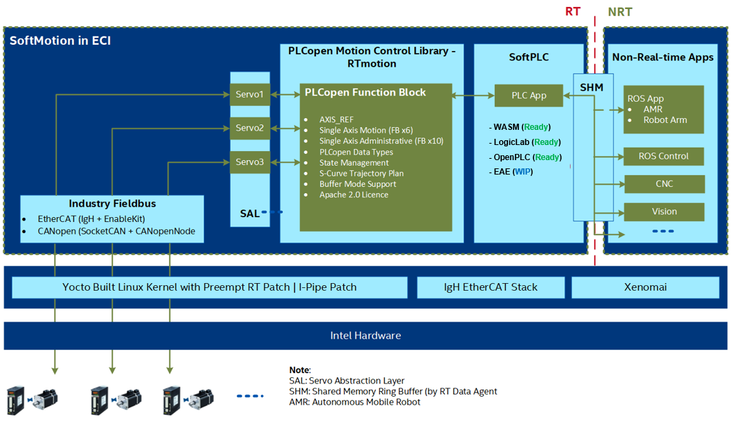
The following sections provide overview on how to use the RTmotion function blocks to develop motion control applications for industrial automation and robotics.
Note
For the detailed information about RTmotion, Please visit RTmotion documentation.
Example Tutorials using Industrial Motion-Control ROS2 Gateway#
The Industrial Motion-Control ROS2 Gateway is the communication bridge between DDS/RSTP wire-protocol ROS2 implementation and Motion Control (MC) IEC-61131-3 standard Intel implementation. It subscribes velocity commands (commonly from Navigation2 stack) and joint trajectories (commonly from MoveIt2 stack), communicates RT Domain through Shared Ring Buffer, and gathers the robot’s status (AMR’s odometry or industrial arm’s joint state) and publishes to ROS domain.
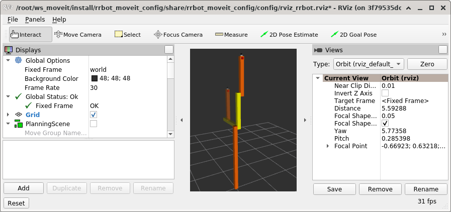
Launch RRBot 2-axis Robotic Arm ROS2 tutorial#
This tutorial monitors and controls the RRBot (Revolute-Revolute Manipulator Robot), a double inverted pendulum robots-arm, within the ROS2 framework. It demonstrates motion-control concepts using a simple 3-linkage, 2-joint arm.
Note
This demo uses the Shared Memory Ring Buffer Library libshmringbuf from the Real-time Data Agent, and requires root permissions to setup the shared memory. As such, sudo -i will be used to get elevated permissions.
Install and Setup ROS2, if not already completed.
Install PLCopen Motion Control:
$ sudo apt install pciutils plcopen-databus libshmringbuf-dev libshmringbuf rt-data-agent ros-humble-controller-manager ros-humble-rrbot-bringup ros-humble-rrbot-moveit-demo
Open a terminal and run the PLCopen IEC-61131-3 motion-control driver:
$ isolcpus=$(cat /sys/devices/system/cpu/isolated)
$ sudo taskset -c ${isolcpus:-1,3} /opt/plcopen/plc_rt_rrbot -t 3600 -i 1000
Note: Replace
/opt/plcopen/plc_rt_rrbotwith/opt/plcopen/plc_rt_rrbot_igh -n <path_to_ethercat_eni_file>to run this demo using two IEC-61158 EtherCAT servo-controlled joint.Open a second terminal with elevated permissions:
$ sudo -i
In the second terminal, setup the ROS2 environment and run the RRBot ROS2 demo:
$ source /opt/ros/humble/setup.bash
$ export ROS_DOMAIN_ID=31
$ ros2 launch rrbot_bringup rrbot_moveit_demo.launch.py
Expected Result:
MoveIt2 starts correctly without exiting.
Note: The command is correctly executed if no “Error” messages are printed (some warnings might be printed due to missing data). The following is a sample result:
[INFO] [launch]: All log files can be found below /root/.ros/log/2022-03-09-18-35-23-491029-2c3d06ed879c-62
[INFO] [launch]: Default logging verbosity is set to INFO
[INFO] [robot_state_publisher-1]: process started with pid [64]
[INFO] [rviz2-2]: process started with pid [66]
[INFO] [run_moveit_cpp-3]: process started with pid [68]
[INFO] [ros2_control_node-4]: process started with pid [79]
[INFO] [ros2 run controller_manager spawner.py joint_trajectory_controller-5]: process started with pid [82]
[INFO] [ros2 run controller_manager spawner.py joint_state_broadcaster-6]: process started with pid [85]
[robot_state_publisher-1] Parsing robot urdf xml string.
[robot_state_publisher-1] Link base_link had 1 children
[robot_state_publisher-1] Link link1 had 1 children
[robot_state_publisher-1] Link link2 had 3 children
[robot_state_publisher-1] Link camera_link had 1 children
[robot_state_publisher-1] Link camera_link_optical had 0 children
[robot_state_publisher-1] Link hokuyo_link had 0 children
[robot_state_publisher-1] Link tool_link had 0 children
……
[run_moveit_cpp-3] [INFO] [1646850933.957900579] [moveit_cpp_demo]: arm.execute()
[run_moveit_cpp-3] [INFO] [1646850933.958014839] [moveit_ros.trajectory_execution_manager]: Validating trajectory with allowed_start_tolerance 0.01
[run_moveit_cpp-3] [INFO] [1646850933.961465153] [moveit_ros.trajectory_execution_manager]: Starting trajectory execution ...
[run_moveit_cpp-3] [INFO] [1646850933.961516544] [moveit.simple_controller_manager.follow_joint_trajectory_controller_handle]: sending trajectory to joint_trajectory_controller
[ros2_control_node-4] [INFO] [1646850933.961809177] [joint_trajectory_controller]: Received new action goal
[ros2_control_node-4] [INFO] [1646850933.961854996] [joint_trajectory_controller]: Accepted new action goal
[run_moveit_cpp-3] [INFO] [1646850933.972377391] [moveit.simple_controller_manager.follow_joint_trajectory_controller_handle]: joint_trajectory_controller started execution
[run_moveit_cpp-3] [INFO] [1646850933.972410502] [moveit.simple_controller_manager.follow_joint_trajectory_controller_handle]: Goal request accepted!
[ros2_control_node-4] [INFO] [1646850936.278047163] [joint_trajectory_controller]: Goal reached, success!
[run_moveit_cpp-3] [INFO] [1646850936.279264357] [moveit.simple_controller_manager.follow_joint_trajectory_controller_handle]: Controller joint_trajectory_controller successfully finished
[run_moveit_cpp-3] [INFO] [1646850936.308323717] [moveit_ros.trajectory_execution_manager]: Completed trajectory execution with status SUCCEEDED ...
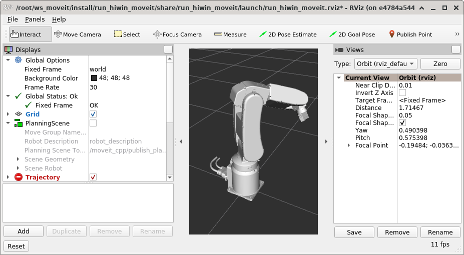
Launch HIWIN 6-axis Robotic Arm ROS2 tutorial#
This demo allows you to monitor and control the following HIWIN industrial robots within the ROS2 framework:
XEG16 electric gripperXEG32 electric gripperXEG64 electric gripper
Note
The HIWIN robot controller’s HRSS software must be be updated to at least version 3.2.16
This demo uses the Shared Memory Ring Buffer Library libshmringbuf from the Real-time Data Agent, and requires root permissions to setup the shared memory. As such, sudo -i will be used to get elevated permissions.
Install and Setup ROS2, if not already completed.
Install PLCopen Motion Control, ROS2 HIWIN databus messages with IEC-61131-3 motion motion-control demo, and ROS2 HIWIN Moveit launcher:
$ sudo apt install pciutils plcopen-databus libshmringbuf-dev libshmringbuf
$ sudo apt install ros-humble-run-hiwin-plc
$ sudo apt install ros-humble-run-hiwin-moveit
Open a terminal and run the Robot-ARM PLCopen IEC-61131-3 motion-control driver:
$ isolcpus=$(cat /sys/devices/system/cpu/isolated)
$ sudo taskset -c ${isolcpus:-1,3} /opt/plcopen/plc_rt_robot_arm_rtmotion -t 3600 -i 1000
Open a second terminal with elevated permissions:
$ sudo -i
In the second terminal, setup the ROS2 environment and run the ROS2 HIWIN databus messages with IEC-61131-3 motion motion-control demo:
$ source /opt/ros/humble/setup.bash
$ export ROS_DOMAIN_ID=31
$ ros2 run run_hiwin_plc run_hiwin_plc
Open a third terminal with elevated permissions:
$ sudo -i
In the third terminal, setup the ROS2 environment and run the ROS2 HIWIN Moveit launch file:
$ source /opt/ros/humble/setup.bash
$ export ROS_DOMAIN_ID=31
$ ros2 launch run_hiwin_plc run_hiwin_plc.launch.py
The demo begins by computing a simple motion plan which is visualized via a transparent RobotState display. This step alone involves a large number of components, such as IK, collision checking, planning scene, robot model, OMPL planning plugin and planner adapters. Immediately after, the trajectory is executed on the HIWIN ros2_control hardware interface.
Expected Result:
MoveIt2 and other ROS2 nodes start correctly without errors if RViz GUI is active and shows a robot arm moving periodically.
Tip
If no messages are displayed on the third terminal, verify that the environment variable
ROS_DOMAIN_IDhas been properly set to the same value in both terminal environments.Note: The command is correctly executed if no “Error” messages are printed (some warnings might be printed due to missing data). The following is a sample result:
[INFO] [launch]: All log files can be found below /home/root/.ros/log/2020-12-01-06-23-24-352240-ecs-intel-4273-3533
[INFO] [launch]: Default logging verbosity is set to INFO
/usr/share/hiwin_robot_moveit_config/xacros/hiwin_robot_and_gripper.urdf
/usr/share/hiwin_robot_moveit_config/srdf/hiwin_robot.srdf
/usr/share/hiwin_robot_moveit_config/config/kinematics.yaml
/usr/share/run_hiwin_plc/launch/run_hiwin_plc.launch.py:25: YAMLLoadWarning: calling yaml.load() without Loader=... is deprecated, as the default Loader is unsafe. Please read https://msg.pyyaml.org/load for full details.
  return yaml.load(file)
/usr/share/run_hiwin_moveit/config/controllers.yaml
/usr/share/hiwin_robot_moveit_config/config/ompl_planning.yaml
[INFO] [robot_state_publisher-1]: process started with pid [3535]
[INFO] [static_transform_publisher-2]: process started with pid [3537]
[INFO] [run_hiwin_moveit-3]: process started with pid [3539]
……
[run_hiwin_moveit-3] [INFO] [1606803829.707921557] [moveit_cpp_demo]: Trajectory status: 1
[run_hiwin_moveit-3] [INFO] [1606803831.708016640] [moveit_cpp_demo]: Set goal 2
[run_hiwin_moveit-3] [INFO] [1606803831.708051094] [moveit_cpp_demo]: Plan to goal
[run_hiwin_moveit-3] [INFO] [1606803831.708563914] [moveit.ompl_planning.model_based_planning_context]: Planner configuration 'manipulator' will use planner 'geometric::RRTConnect'. Additional configuration parameters will be set when the planner is constructed.
[run_hiwin_moveit-3] [INFO] [1606803831.723452924] [ompl]: /usr/src/debug/ompl/1.5.0-1-r0/git/src/ompl/geometric/planners/rrt/src/RRTConnect.cpp:354 - manipulator/manipulator: Created 5 states (2 start + 3 goal)
[run_hiwin_moveit-3] [INFO] [1606803831.723565262] [ompl]: /usr/src/debug/ompl/1.5.0-1-r0/git/src/ompl/tools/multiplan/src/ParallelPlan.cpp:135 - ParallelPlan::solve(): Solution found by one or more threads in 0.000756 seconds
[run_hiwin_moveit-3] [INFO] [1606803831.726168559] [ompl]: /usr/src/debug/ompl/1.5.0-1-r0/git/src/ompl/geometric/src/SimpleSetup.cpp:179 - SimpleSetup: Path simplification took 0.002559 seconds and changed from 3 to 2 states
[run_hiwin_moveit-3] [INFO] [1606803831.728662079] [moveit_cpp_demo]: Sending the trajectory for execution
Launch AGV ROS2 tutorial#
This tutorial allows monitors and controls an AGV (Automated Guided Vehicle) using the EtherCAT wired-protocol control on four Mecanum wheel-drive chassis within the ROS2 framework. YDLidar Communication Protocol for ROS2 is used for ydlidar devices to configure LiDAR in the ROS2 environment.
Note
This demo uses the Shared Memory Ring Buffer Library libshmringbuf from the Real-time Data Agent, and requires root permissions to setup the shared memory. As such, sudo -i will be used to get elevated permissions.
Install and Setup ROS2, if not already completed.
Install PLCopen Motion Control and the ROS2 AGVM databus messages with IEC-61131-3 motion motion-control demo:
$ sudo apt install pciutils plcopen-databus libshmringbuf-dev libshmringbuf
$ sudo apt install ros-humble-agvm
Run the Robot-ARM PLCopen IEC-61131-3 motion-control driver:
$ isolcpus=$(cat /sys/devices/system/cpu/isolated)
$ sudo taskset -c ${isolcpus:-1,3} /opt/plcopen/plc_rt_amr_rtmotion -t 3600 -i 1000
Note:
/opt/plcopen/plc_rt_amr_rtmotion_symgis a sample application using EtherCAT to control the Mecanum Wheel Platform.Open a second terminal with elevated permissions:
$ sudo -i
In the second terminal, setup the ROS2 environment and run the ROS2 AGVM databus messages with IEC-61131-3 motion motion-control demo:
$ source /opt/ros/humble/setup.bash
$ export ROS_DOMAIN_ID=31
$ ros2 launch agvm agvm_base.launch.py
Expected Result:
ROS2 nodes start correctly, without exiting.
Note: Since the joystick is disconnected, it is normal to see the error
[ERROR] [1657850097.527093048] [agvm_joystick_node]: Cannot open /dev/input/js0 -1!.Note: The command is correctly executed if no “Error” messages are printed (some warnings might be printed due to missing data). The following is a sample result:
[INFO] [launch]: All log files can be found below /root/.ros/log/2022-07-15-01-54-57-311770-d2d206ef9a2c-117
[INFO] [launch]: Default logging verbosity is set to INFO
[INFO] [robot_state_publisher-1]: process started with pid [119]
[INFO] [joint_state_publisher-2]: process started with pid [121]
[INFO] [agvm_plcshm_node-3]: process started with pid [123]
[INFO] [agvm_joystick_node-4]: process started with pid [125]
[INFO] [ydlidar_node-5]: process started with pid [127]
[robot_state_publisher-1] Parsing robot urdf xml string.
[robot_state_publisher-1] Link base_link had 1 children
[robot_state_publisher-1] Link base_scan had 0 children
……
[agvm_plcshm_node-3] [INFO] [1657850097.490716583] [agvm_plcshm_node]: AgvmPlcShmNode initial complete.
[agvm_plcshm_node-3] [INFO] [1657850097.500794279] [agvm_plcshm_node]: AGV cmd: 0.000000 0.000000 0.000000
[agvm_plcshm_node-3] [INFO] [1657850097.500855464] [agvm_plcshm_node]: AGV pose: 0.000000 0.000000 345.860687
[agvm_plcshm_node-3] [INFO] [1657850097.500876573] [agvm_plcshm_node]: AGV vel: 0.000000 0.000000 345860.687500
[agvm_plcshm_node-3] [INFO] [1657850097.500895089] [agvm_plcshm_node]: AGV mOdom: 0.000000 0.000000 34586.068726
[agvm_plcshm_node-3]
Open a third terminal with elevated permissions:
$ sudo -i
In the third terminal, setup the ROS2 environment and run the following command:
$ source /opt/ros/humble/setup.bash
$ export ROS_DOMAIN_ID=31
$ ros2 topic pub -1 /cmd_vel geometry_msgs/msg/Twist "{linear: {x: -0.1}, angular: {z: -0.1}}"
Note:
linear: {x: -0.1}is the linear velocity(m/s) for AMR.angular: {x: -0.1}is the angular velocity(rad/s) for AMR.Expected Result:
Variables
AGV cmd/pose/vel/mOdomin the second terminal console will be refreshed.
Example Applications#
Applications for Industrial Automation#
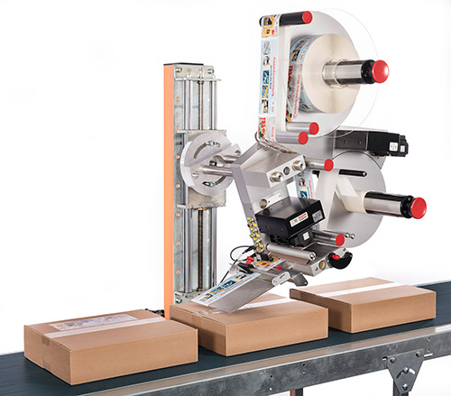
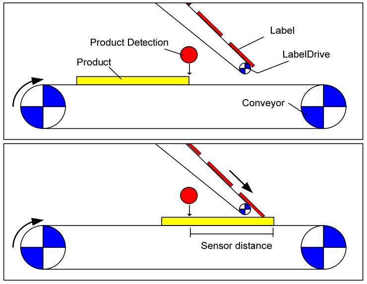
Labeling is commonly seen in the automation of the pharmaceuticals, beverage, and chemicals packaging. As shown in the following figures (left [1] and right [2]), the task is to place a label at a particular position on a product. The application has two drives, one to feed the product via a conveyor belt and another to feed the labels and to place the labels on the products. The labeling process is triggered by a position detection sensor. From the detection of the product to the start of the label movement there is a delay depending on the velocity of the conveyor, the position of the sensor, and the position of the label on the product.
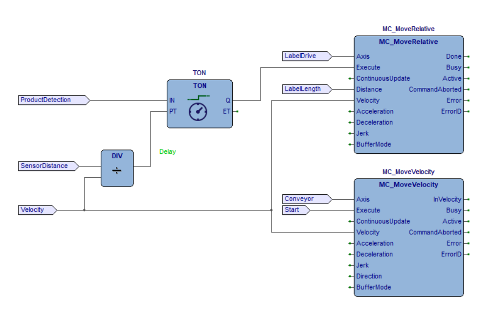
RTmotion motion control function blocks can be used with the SoftPLC systems, for example, CODESYS, MULTIPROG, and LogicLab, to solve this kind of problems. SoftPLC generally supports five programming languages for the application development according to the IEC 61131-3 standard: Instruction List (IL), Structured Text (ST), Function Block Diagram (FBD), Ladder Diagram (LD), and Sequential Function Chart (SFC). The following FBD [2] shows a way to solve this task. Both axes move with the same velocity setpoint. The delay for On Delay Timer (TON) is calculated from the sensor distance and the velocity. After a labeling step, the LabelDrive stops again and waits for the next trigger, while the conveyor continuously moves.
The labeling application can also be implemented as an ST program:
Click to view the ST program
(* PLC configuration *)
CONFIGURATION DefaultCfg
  VAR_GLOBAL
    Product_Detection   AT %MX3.0.0: BOOL;
    Start               AT %MX3.1.0: BOOL;
    Label_Length        AT %ML3.200: REAL;
    Sensor_Distance     AT %ML3.204: REAL;
    Velocity            AT %ML3.208: REAL;
  END_VAR

  // Schedule the main program to be executed every 1 ms
  TASK Tick(INTERVAL := T#1ms);

  PROGRAM Main WITH Tick : Labeling_Example_Code;
END_CONFIGURATION

(* Labeling machine program *)
PROGRAM Labeling_Example_Code
  VAR_EXTERNAL
    Product_Detection  : BOOL;
    Start              : BOOL;
    Label_Length:      : REAL;
    Sensor_Distance:   : REAL;
    Velocity           : REAL;
  END_VAR

  VAR
    MC_Power_1:         MC_Power;
    MC_Power_2:         MC_Power;
    Label_Drive:        AXIS_REF;
    Conveyor:           AXIS_REF;
    MC_MoveVelocity_1:  MC_MoveVelocity;
    MC_MoveRelative_1:  MC_MoveRelative;
    Delay_Timer:        TON;
  END_VAR

  MC_Power_1(Axis := Label_Drive,
            Enable := True,
            EnablePositive := True,
            EnableNegative := True);

  MC_Power_2(Axis := Conveyor,
            Enable := True,
            EnablePositive := True,
            EnableNegative := True);

  Delay_Timer(IN := Product_Detection,
              PT := REAL_TO_TIME(IN := Sensor_Distance / Velocity));

  IF MC_Power_1.Status AND MC_Power_1.Valid THEN
    MC_MoveRelative_1(Axis := Label_Drive,
                      Execute := Delay_Timer.Q,
                      Position := Label_Length,
                      Velocity := Velocity);
  END_IF;

  IF MC_Power_2.Status AND MC_Power_2.Valid THEN
    MC_MoveVelocity_1(Axis := Conveyor,
                      Execute := Start,
                      Velocity := Velocity);
  END_IF;
END_PROGRAM
A sample is provided which converts the ST program into a C++ program and drives two Inovance EtherCAT servo motors. Run by the following command:
$ /opt/plcopen/duo_rtmotion_demo -n inovance_duo_1ms.xml -i 1000
where, -n specifies the EtherCAT ENI file, which is generated from a vendor-specific EtherCAT ESI file. For more information, refer to EtherCAT Enablekit. -i specifies the real-time cycle time in microseconds.
To run a real labeling application, input the FBD or ST program to the SoftPLC system, integrate the RTmotion function blocks with the SoftPLC system, and connect the function blocks to the servo motors through the IgH* EtherCAT master stack. Then, use the SoftPLC system to compile and run the program to control the labeling machine.
SoftPLC systems usually provide an interface to integrate external function blocks written in C or C++. The integration includes three steps:
Develop a new derived servo class from the
RTmotion/Servoclass. Override all the virtual functions of theRTmotion/Servoclass by using the SoftPLC provided EtherCAT master stack API to control a servo motor.Use SoftPLC SDK to create custom function blocks that match the input/output of
RTmotion::Function Blocks.Register the initialization of
RTmotion::Axes,RTmotion::Function BlocksandRTmotion::Derived Servosto the PLC initialization function. Register therunCyclefunctions ofRTmotion::AxesandRTmotion::Function Blocksto the PLC runtime functions.
When running the FBD or ST program, the function blocks will be called to send the trajectory planning commands to control the servo motors.
Applications for Robotics#
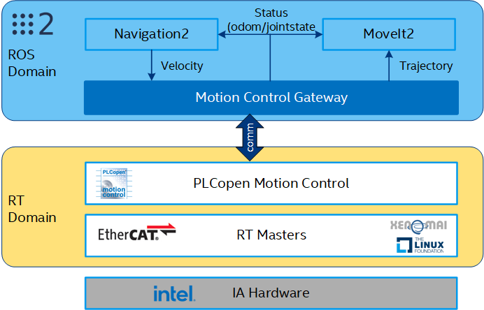
Robot Operating System (ROS/2) [3] is the worldwide de facto standard software middleware for developing intelligent robot applications. With specially designed interface to ROS/2, RTmotion motion control function blocks can be combined with the ROS/2 Navigation and MoveIt to develop applications for the (AMR) and industrial robots, as shown below. This opens up the potential that real-time low-level control and intelligent high-level control to run seamlessly on a single Intel platform.
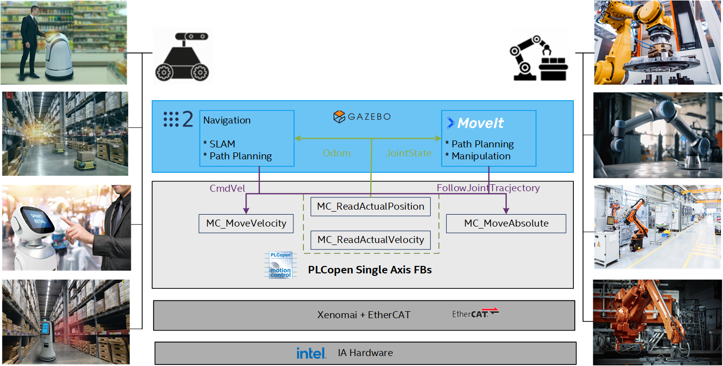
The concept has been proven in the joint-lab project between SYMG and Intel through controlling an omni-directional AMR with four servo motors by integrating ROS2 navigation, SoftPLC (commercial and open sourced), PLCopen motion function blocks, and IgH EtherCAT master stack, and running the whole software stack on an Intel optimized real-time Linux kernel.
As shown in the above figure, ROS2 navigation plans the global path routine and local trajectory for the AMR to move. When AMR moves, the velocity command cmd_vel, calculated by ROS2 Navigation, is transmitted to the SoftPLC system through the shared memory. This guarantees the efficient communication and good separation between real-time and non real-time processes. The velocity command cmd_vel includes three components indicating the velocities translating forward (VelX), translating sideways (VelY), and rotating round the center of mass (VelRZ) on the 2-D plane. The AMR velocity command is parsed and split into the velocities of four Mecanum [4] wheels (UL, UR, LL, LR). The following figure shows the details of this split process. The velocity command of each wheel is input into a MC_MoveVelocty function block to execute. The MC_MoveVelocity function block makes path interpolation between the velocity inputs and sends the command to the servo motor through the IgH EtherCAT stack. At the same time, the SoftPLC calls the function blocks MC_ReadActualPosition and MC_ReadActualVelocity to read the wheel velocity, and synthesize the information into the odometry of AMR. The odometry information is then transmitted back to ROS2 navigation through the shared memory for the SLAM calculation.
The following is the ST program for this application, which is configured to run in 1ms cycle:
Click to view the ST program
(* Split the AMR velocity into the wheel velocities *)
FUNCTION_BLOCK AGVM_VelCartesian2Wheels
  VAR_INPUT
    VelX :    LREAL;
    VelY :    LREAL;
    VelRZ :   LREAL;
  END_VAR

  VAR_OUTPUT
    UL :      LREAL;
    UR :      LREAL;
    LL :      LREAL;
    LR :      LREAL;
  END_VAR

  VAR_EXTERNAL
    WheelHDistance :  LREAL;(**)
    WheelVDistance :  LREAL;(**)
  END_VAR

  VAR
    VelLZ :   LREAL;
  END_VAR

  VelLZ := VelRZ * ((WheelHDistance + WheelVDistance) / LREAL#2.0);

  UL := VelX - VelY - VelLZ;
  UR := VelX + VelY + VelLZ;
  LL := VelX + VelY - VelLZ;
  LR := VelX - VelY + VelLZ;
END_FUNCTION_BLOCK

(* Synthesize the wheel velocities into the AMR velocity *)
FUNCTION_BLOCK AGVM_VelWheels2Cartesian
  VAR_INPUT
    UL :      LREAL;
    UR :      LREAL;
    LL :      LREAL;
    LR :      LREAL;
  END_VAR

  VAR_OUTPUT
    VelX :    LREAL;
    VelY :    LREAL;
    VelRZ :   LREAL;
  END_VAR

  VAR_EXTERNAL
    WheelHDistance :  LREAL;(**)
    WheelVDistance :  LREAL;(**)
  END_VAR

  VelX := (UL + UR + LL + LR) / LREAL#4.0;

  VelY := (-UL + UR + LL - LR) / LREAL#4.0;
  VelRZ := (-UL + UR - LL + LR) / LREAL#4.0 / ((WheelHDistance + WheelVDistance) / LREAL#2.0);
END_FUNCTION_BLOCK

(* Global variables *)
VAR_GLOBAL
  PLC_SYS_TICK_CNT    AT %MD1.0 :     UDINT;
  PLC_TASK_DEFINED    AT %MW1.4 :     INT;
  PLCMODE_ON  AT %MX1.2016.0 :        BOOL;(*TRUE : current PLC mode is ON*)
  PLCMODE_LOADING     AT %MX1.2017.0 :        BOOL;(*TRUE : current PLC mode is LOADING*)
  PLCMODE_STOP        AT %MX1.6.0 :   BOOL;(*TRUE : current PLC mode is STOP*)
  PLCMODE_RUN AT %MX1.7.0 :   BOOL;(*TRUE : current PLC mode is RUN*)
  PLCMODE_HALT        AT %MX1.8.0 :   BOOL;(*TRUE : current PLC mode is HALT*)
  PLC_TICKS_PER_SEC   AT %MW1.2000 :  UINT;
  PLC_MAX_ERRORS      AT %MD1.2004 :  UDINT;
  PLC_ERRORS  AT %MD1.2008 :  UDINT;
  PLC_TASK_AVAILABLE  AT %MW1.2012 :  INT;
  PLC_SYSTASK_AVAILABLE       AT %MW1.2016 :  INT;
  PLCDEBUG_FORCE      AT %MX1.2018.0 :        BOOL;(*TRUE : current PLC mode is POWER on*)
  PLCDEBUG_BPSET      AT %MX1.2019.0 :        BOOL;(*TRUE : one or more*)
  PLCDEBUG_POWERFLOW  AT %MX1.2020.0 :        BOOL;(*TRUE : current PLC mode is POWER on*)
  WheelVDistance :    LREAL := 0.483;(*Distance between the front and back wheels*)
  WheelHDistance :    LREAL := 0.371;(*Distance between the two side wheels*)
END_VAR

(* Main program *)
PROGRAM main
  VAR
    Acc :     LREAL := 2.0;
    MC_Power_1 :      MC_Power;
    MC_Power_2 :      MC_Power;
    MC_Power_3 :      MC_Power;
    MC_Power_4 :      MC_Power;
    PowStat : BOOL;
    AxisLL :  DINT := 3;
    AxisLR :  DINT := 4;
    AxisUL :  DINT := 1;
    AxisUR :  DINT := 2;
    RatioLimit :      LREAL := 1.0;
    VAxisULVel :      LREAL;
    VAxisURVel :      LREAL;
    VAxisLLVel :      LREAL;
    VAxisLRVel :      LREAL;
    VAxisMaxVel :     LREAL;
    AxisVelLimit :    LREAL := 0.75;
    MC_EmergencyStop_1 :      MC_EmergencyStop;
    MC_Reset_1 :      MC_Reset;
    TransH :  LREAL;
    TransV :  LREAL;
    Twist :   LREAL;
    MC_Reset_2 :      MC_Reset;
    MC_Reset_3 :      MC_Reset;
    MC_Reset_4 :      MC_Reset;
    ENABLE_FLAG :     BOOL;
    MC_Halt_2 :       MC_Halt;
    MC_Halt_3 :       MC_Halt;
    MC_Halt_4 :       MC_Halt;
    MC_MoveVelocity_2 :       MC_MoveVelocity;
    MC_MoveVelocity_3 :       MC_MoveVelocity;
    MC_MoveVelocity_4 :       MC_MoveVelocity;
    MC_Halt_1 :       MC_Halt;
    MC_MoveVelocity_1 :       MC_MoveVelocity;
    SHM_PosX  AT %ML3.200 :   LREAL := 0.0;
    SHM_PosY  AT %ML3.208 :   LREAL := 0.0;
    SHM_PosRZ AT %ML3.216 :   LREAL := 0.0;
    SHM_VelX  AT %ML3.224 :   LREAL := 0.0;
    SHM_VelY  AT %ML3.232 :   LREAL := 0.0;
    SHM_VelRZ AT %ML3.240 :   LREAL := 0.0;
    SHM_Error AT %MX3.248.0 : BOOL;
    MC_ReadAxisError_1 :      MC_ReadAxisError;
    SHM_Enable        AT %MX3.100.0 : BOOL;
    SHM_EmergStop     AT %MX3.101.0 : BOOL;
    SHM_TransH        AT %ML3.102 :   LREAL := 0.0;
    SHM_Twist AT %ML3.118 :   LREAL := 0.0;
    SHM_TransV        AT %ML3.110 :   LREAL := 0.0;
    MC_SetPosition_1 :        MC_SetPosition;
    MC_ReadActualPosition_1 : MC_ReadActualPosition;
    AGVM_VelCartesian2Wheels_1 :      AGVM_VelCartesian2Wheels;
    MC_ReadActualVelocity_1 : MC_ReadActualVelocity;
    MC_ReadActualVelocity_2 : MC_ReadActualVelocity;
    MC_ReadActualVelocity_3 : MC_ReadActualVelocity;
    MC_ReadActualVelocity_4 : MC_ReadActualVelocity;
    AGVM_VelWheels2Cartesian_1 :      AGVM_VelWheels2Cartesian;
    AxisULPos :       LREAL;
    MC_ReadActualPosition_2 : MC_ReadActualPosition;
    MC_ReadActualPosition_3 : MC_ReadActualPosition;
    MC_ReadActualPosition_4 : MC_ReadActualPosition;
    AxisURPos :       LREAL;
    AxisLLPos :       LREAL;
    AxisLRPos :       LREAL;
    AGVM_VelWheels2Cartesian_2 :      AGVM_VelWheels2Cartesian;
    AxisULErr :       WORD;
    AxisURErr :       WORD;
    AxisLLErr :       WORD;
    AxisLRErr :       WORD;
    INIT :    BOOL := TRUE;
    MC_MoveAbsolute_1 :       MC_MoveAbsolute;
  END_VAR

  TransV := SHM_TransV;
  TransH := SHM_TransH;
  Twist := SHM_Twist;

  IF SHM_EmergStop THEN
    SHM_EmergStop := FALSE;
    SHM_Enable := FALSE;
    ENABLE_FLAG:=FALSE;
    MC_EmergencyStop_1(Execute:=FALSE);
    MC_EmergencyStop_1(Axis:=AxisUL,Execute:=TRUE);
    MC_EmergencyStop_1(Execute:=FALSE);
    MC_EmergencyStop_1(Axis:=AxisUR,Execute:=TRUE);
    MC_EmergencyStop_1(Execute:=FALSE);
    MC_EmergencyStop_1(Axis:=AxisLL,Execute:=TRUE);
    MC_EmergencyStop_1(Execute:=FALSE);
    MC_EmergencyStop_1(Axis:=AxisLR,Execute:=TRUE);
  END_IF;

  IF SHM_Enable THEN
    SHM_Enable := FALSE;
    IF NOT PowStat THEN
      MC_Reset_1(Execute:=FALSE);
      MC_Reset_2(Execute:=FALSE);
      MC_Reset_3(Execute:=FALSE);
      MC_Reset_4(Execute:=FALSE);
      ENABLE_FLAG:=TRUE;
    END_IF;
  END_IF;

  IF ENABLE_FLAG THEN
    MC_Reset_1(Axis:=AxisUL,Execute:=TRUE);
    MC_Reset_2(Axis:=AxisUR,Execute:=TRUE);
    MC_Reset_3(Axis:=AxisLL,Execute:=TRUE);
    MC_Reset_4(Axis:=AxisLR,Execute:=TRUE);

    IF MC_Reset_1.Done AND MC_Reset_2.Done AND MC_Reset_3.Done AND MC_Reset_4.Done THEN
      ENABLE_FLAG := FALSE;
    END_IF;
  END_IF;

  MC_Power_1(Axis:=AxisUL,Enable:=TRUE,EnablePositive:=TRUE,EnableNegative:=TRUE);
  MC_Power_2(Axis:=AxisUR,Enable:=TRUE,EnablePositive:=TRUE,EnableNegative:=TRUE);
  MC_Power_3(Axis:=AxisLL,Enable:=TRUE,EnablePositive:=TRUE,EnableNegative:=TRUE);
  MC_Power_4(Axis:=AxisLR,Enable:=TRUE,EnablePositive:=TRUE,EnableNegative:=TRUE);

  PowStat := MC_Power_1.Status AND MC_Power_1.Valid AND
        MC_Power_2.Status AND MC_Power_2.Valid AND
        MC_Power_3.Status AND MC_Power_3.Valid AND
        MC_Power_4.Status AND MC_Power_4.Valid;

  IF PowStat THEN
    IF INIT THEN
      MC_SetPosition_1(Execute:=FALSE);
      MC_SetPosition_1(Axis:=AxisUL,Execute:=TRUE,Position:=LREAL#0.0,Relative:=FALSE,Source:=DINT#1);
      MC_SetPosition_1(Execute:=FALSE);
      MC_SetPosition_1(Axis:=AxisUR,Execute:=TRUE,Position:=LREAL#0.0,Relative:=FALSE,Source:=DINT#1);
      MC_SetPosition_1(Execute:=FALSE);
      MC_SetPosition_1(Axis:=AxisLL,Execute:=TRUE,Position:=LREAL#0.0,Relative:=FALSE,Source:=DINT#1);
      MC_SetPosition_1(Execute:=FALSE);
      MC_SetPosition_1(Axis:=AxisLR,Execute:=TRUE,Position:=LREAL#0.0,Relative:=FALSE,Source:=DINT#1);
      SHM_PosX:=LREAL#0.0;
      SHM_PosY:=LREAL#0.0;
      SHM_PosRZ:=LREAL#0.0;
      AxisULPos:=LREAL#0.0;
      AxisURPos:=LREAL#0.0;
      AxisLLPos:=LREAL#0.0;
      AxisLRPos:=LREAL#0.0;
      INIT:=FALSE;
    END_IF;

    AGVM_VelCartesian2Wheels_1(VelX:=TransV,VelY:=TransH,VelRZ:=Twist);
    VAxisULVel:=AGVM_VelCartesian2Wheels_1.UL;
    VAxisURVel:=AGVM_VelCartesian2Wheels_1.UR;
    VAxisLLVel:=AGVM_VelCartesian2Wheels_1.LL;
    VAxisLRVel:=AGVM_VelCartesian2Wheels_1.LR;

    RatioLimit := LREAL#1.0;
    VAxisMaxVel := ABS(VAxisULVel);

    IF VAxisMaxVel < ABS(VAxisURVel) THEN
      VAxisMaxVel := ABS(VAxisURVel);
    END_IF;

    IF VAxisMaxVel < ABS(VAxisLLVel) THEN
      VAxisMaxVel := ABS(VAxisLLVel);
    END_IF;

    IF VAxisMaxVel < ABS(VAxisLRVel) THEN
      VAxisMaxVel := ABS(VAxisLRVel);
    END_IF;

    IF VAxisMaxVel = LREAL#0.0 THEN
      RatioLimit := LREAL#0.0;
    ELSIF VAxisMaxVel > AxisVelLimit THEN
      RatioLimit := AxisVelLimit / VAxisMaxVel;
    END_IF;

    IF VAxisULVel = LREAL#0.0 THEN
      MC_Halt_1(Execute:=FALSE);
      MC_Halt_1(Axis:=AxisUL,Execute:=TRUE,Deceleration:=Acc);
    ELSE
      MC_MoveVelocity_1(Execute:=FALSE);
      MC_MoveVelocity_1(Axis:=AxisUL,Execute:=TRUE,Velocity:=VAxisULVel * RatioLimit,Acceleration:=Acc,Deceleration:=Acc);
    END_IF;

    IF VAxisURVel = LREAL#0.0 THEN
      MC_Halt_2(Execute:=FALSE);
      MC_Halt_2(Axis:=AxisUR,Execute:=TRUE,Deceleration:=Acc);
    ELSE
      MC_MoveVelocity_2(Execute:=FALSE);
      MC_MoveVelocity_2(Axis:=AxisUR,Execute:=TRUE,Velocity:=VAxisURVel * RatioLimit,Acceleration:=Acc,Deceleration:=Acc);
    END_IF;

    IF VAxisLLVel = LREAL#0.0 THEN
      MC_Halt_3(Execute:=FALSE);
      MC_Halt_3(Axis:=AxisLL,Execute:=TRUE,Deceleration:=Acc);
    ELSE
      MC_MoveVelocity_3(Execute:=FALSE);
      MC_MoveVelocity_3(Axis:=AxisLL,Execute:=TRUE,Velocity:=VAxisLLVel * RatioLimit,Acceleration:=Acc,Deceleration:=Acc);
    END_IF;

    IF VAxisLRVel = LREAL#0.0 THEN
      MC_Halt_4(Execute:=FALSE);
      MC_Halt_4(Axis:=AxisLR,Execute:=TRUE,Deceleration:=Acc);
    ELSE
      MC_MoveVelocity_4(Execute:=FALSE);
      MC_MoveVelocity_4(Axis:=AxisLR,Execute:=TRUE,Velocity:=VAxisLRVel * RatioLimit,Acceleration:=Acc,Deceleration:=Acc);
    END_IF;
  END_IF;

  MC_ReadActualVelocity_1(Axis:=AxisUL,Enable:=TRUE);
  MC_ReadActualVelocity_2(Axis:=AxisUR,Enable:=TRUE);
  MC_ReadActualVelocity_3(Axis:=AxisLL,Enable:=TRUE);
  MC_ReadActualVelocity_4(Axis:=AxisLR,Enable:=TRUE);

  AGVM_VelWheels2Cartesian_1(
    UL:=MC_ReadActualVelocity_1.Velocity,
    UR:=MC_ReadActualVelocity_2.Velocity,
    LL:=MC_ReadActualVelocity_3.Velocity,
    LR:=MC_ReadActualVelocity_4.Velocity);

  SHM_VelX:=AGVM_VelWheels2Cartesian_1.VelX;
  SHM_VelY:=AGVM_VelWheels2Cartesian_1.VelY;
  SHM_VelRZ:=AGVM_VelWheels2Cartesian_1.VelRZ;

  MC_ReadActualPosition_1(Axis:=AxisUL,Enable:=TRUE);
  MC_ReadActualPosition_2(Axis:=AxisUR,Enable:=TRUE);
  MC_ReadActualPosition_3(Axis:=AxisLL,Enable:=TRUE);
  MC_ReadActualPosition_4(Axis:=AxisLR,Enable:=TRUE);

  AGVM_VelWheels2Cartesian_2(
    UL:=MC_ReadActualPosition_1.Position - AxisULPos,
    UR:=MC_ReadActualPosition_2.Position - AxisURPos,
    LL:=MC_ReadActualPosition_3.Position - AxisLLPos,
    LR:=MC_ReadActualPosition_4.Position - AxisLRPos);

  SHM_PosX:=SHM_PosX + (AGVM_VelWheels2Cartesian_2.VelX * COS(SHM_PosRZ) - AGVM_VelWheels2Cartesian_2.VelY * SIN(SHM_PosRZ));
  SHM_PosY:=SHM_PosY + (AGVM_VelWheels2Cartesian_2.VelX * SIN(SHM_PosRZ) + AGVM_VelWheels2Cartesian_2.VelY * COS(SHM_PosRZ));
  SHM_PosRZ:=SHM_PosRZ + AGVM_VelWheels2Cartesian_2.VelRZ;

  AxisULPos:=MC_ReadActualPosition_1.Position;
  AxisURPos:=MC_ReadActualPosition_2.Position;
  AxisLLPos:=MC_ReadActualPosition_3.Position;
  AxisLRPos:=MC_ReadActualPosition_4.Position;

  MC_ReadAxisError_1(Axis:=AxisUL,Enable:=TRUE);
  AxisULErr:=MC_ReadAxisError_1.ErrorID;

  MC_ReadAxisError_1(Axis:=AxisUR,Enable:=TRUE);
  AxisURErr:=MC_ReadAxisError_1.ErrorID;

  MC_ReadAxisError_1(Axis:=AxisLL,Enable:=TRUE);
  AxisLLErr:=MC_ReadAxisError_1.ErrorID;

  MC_ReadAxisError_1(Axis:=AxisLR,Enable:=TRUE);
  AxisLRErr:=MC_ReadAxisError_1.ErrorID;
END_PROGRAM
PLCopen Motion Sanity Checks#
Use these sanity checks to verify your configuration is correct.
Sanity Check #1: On-line S-Curve Algorithm Test#
$ /opt/plcopen/online_scurve_test
Expected Output
[==========] Running 9 tests from 1 test suite.
[----------] Global test environment set-up.
[----------] 9 tests from ScurveTest
[ RUN      ] ScurveTest.Test1
Polynomial coeffs: a0 43.333340, a0 10.000000, a0 0.000000, a0 -5.625028, a0 2.109407, a0 -0.000009
Scurve profile: Tj2a 0.333333, Tj2b 0.333333, Td 1.333333
Scurve termination: sk_e -0.000000, vk_e 0.000002, ak_e -0.011247
[       OK ] ScurveTest.Test1 (1 ms)
[ RUN      ] ScurveTest.Test2
Polynomial coeffs: a0 0.819853, a0 3.933340, a0 5.000000, a0 -5.265315, a0 -0.676768, a0 1.109904
Scurve profile: Tj2a 0.666667, Tj2b 0.333333, Td 1.226667
Scurve termination: sk_e -0.000000, vk_e 0.000011, ak_e -0.032459
[       OK ] ScurveTest.Test2 (0 ms)
[ RUN      ] ScurveTest.Test3
Polynomial coeffs: a0 0.503677, a0 5.432135, a0 2.955000, a0 -7.379425, a0 3.228023, a0 0.143848
Scurve profile: Tj2a 0.530333, Tj2b 0.500000, Td 1.040094
Scurve termination: sk_e -0.000281, vk_e -0.000468, ak_e -0.004274
[       OK ] ScurveTest.Test3 (0 ms)
[ RUN      ] ScurveTest.Test4
Polynomial coeffs: a0 1.538060, a0 5.233840, a0 2.740000, a0 -1.969392, a0 -10.467462, a0 9.302328
Scurve profile: Tj2a 0.488227, Tj2b 0.238894, Td 0.727121
Scurve termination: sk_e -0.000362, vk_e -0.000241, ak_e -0.012134
[       OK ] ScurveTest.Test4 (0 ms)
[ RUN      ] ScurveTest.Test5
Polynomial coeffs: a0 43.090361, a0 9.993340, a0 0.000000, a0 -6.850631, a0 3.713191, a0 -0.260350
Scurve profile: Tj2a 0.333333, Tj2b 0.400000, Td 1.106001
Scurve termination: sk_e -0.000002, vk_e -0.000001, ak_e -0.000026
[       OK ] ScurveTest.Test5 (0 ms)
[ RUN      ] ScurveTest.Test6
Polynomial coeffs: a0 31.188293, a0 9.993340, a0 0.000000, a0 5.528178, a0 -1.977616, a0 -0.042063
Scurve profile: Tj2a 0.333333, Tj2b 0.266667, Td 1.273999
Scurve termination: sk_e -0.019986, vk_e -0.002014, ak_e 0.031347
[       OK ] ScurveTest.Test6 (0 ms)
[ RUN      ] ScurveTest.Test7
Polynomial coeffs: a0 1.532744, a0 14.421760, a0 -3.560000, a0 5.345304, a0 0.326130, a0 -1.078490
Scurve profile: Tj2a 0.570667, Tj2b 0.266667, Td 1.152981
Scurve termination: sk_e -0.019626, vk_e -0.001984, ak_e 0.044019
[       OK ] ScurveTest.Test7 (0 ms)
[ RUN      ] ScurveTest.Test8
Polynomial coeffs: a0 2.742635, a0 1.570000, a0 0.000000, a0 -6.130163, a0 6.063986, a0 -0.011689
Scurve profile: Tj2a 0.006280, Tj2b 0.006280, Td 0.506280
Scurve termination: sk_e -0.000000, vk_e 0.000001, ak_e -0.010276
[       OK ] ScurveTest.Test8 (0 ms)
[ RUN      ] ScurveTest.Test9
Polynomial coeffs: a0 2.443341, a0 6.753340, a0 5.000000, a0 -5.738710, a0 0.443898, a0 0.434246
Scurve profile: Tj2a 0.666667, Tj2b 0.333333, Td 1.508667
Scurve termination: sk_e -0.000000, vk_e 0.000009, ak_e -0.027303
[       OK ] ScurveTest.Test9 (0 ms)
[----------] 9 tests from ScurveTest (4 ms total)

[----------] Global test environment tear-down
[==========] 9 tests from 1 test suite ran. (4 ms total)
[  PASSED  ] 9 tests.
The tests verify the motor trajectory planning under different conditions.
Sanity Check #2: Trajectory Planner Test#
$ /opt/plcopen/planner_test
Expected Output
[==========] Running 8 tests from 1 test suite.
[----------] Global test environment set-up.
[----------] 8 tests from PlannerTest
[ RUN      ] PlannerTest.VelocityUp
Scurve profile: Ta = 1.433333, Tv = 0.000000, Td = 0.000000, Tj1 = 0.333333, Tj2 = 0.000000
[       OK ] PlannerTest.VelocityUp (0 ms)
[ RUN      ] PlannerTest.VelocityDown
Scurve profile: Ta = 1.833333, Tv = 0.000000, Td = 0.000000, Tj1 = 0.333333, Tj2 = 0.000000
[       OK ] PlannerTest.VelocityDown (0 ms)
[ RUN      ] PlannerTest.Example_3_9
[       OK ] PlannerTest.Example_3_9 (0 ms)
[ RUN      ] PlannerTest.Example_3_10
[       OK ] PlannerTest.Example_3_10 (0 ms)
[ RUN      ] PlannerTest.Example_3_11
[       OK ] PlannerTest.Example_3_11 (0 ms)
[ RUN      ] PlannerTest.Example_3_12
[       OK ] PlannerTest.Example_3_12 (0 ms)
[ RUN      ] PlannerTest.Example_3_13
[       OK ] PlannerTest.Example_3_13 (0 ms)
[ RUN      ] PlannerTest.Test_Negative
[       OK ] PlannerTest.Test_Negative (0 ms)
[----------] 8 tests from PlannerTest (5 ms total)

[----------] Global test environment tear-down
[==========] 8 tests from 1 test suite ran. (5 ms total)
[  PASSED  ] 8 tests.
The tests verify the motor trajectory planning under different conditions.
Sanity Check #3: Function Block Test#
$ /opt/plcopen/function_block_test
Expected Output
[==========] Running 8 tests from 1 test suite.
[----------] Global test environment set-up.
[----------] 8 tests from FunctionBlockTest
[ RUN      ] FunctionBlockTest.DemoRelative
Axis initialized.
Function block initialized.
Axis #1 powered on, axis_pos_ = 0.000000
FB test end. Delete axis and servo.
[       OK ] FunctionBlockTest.DemoRelative (2545 ms)
[ RUN      ] FunctionBlockTest.DemoVelocity
Axis initialized.
Function block initialized.
Axis #1 powered on, axis_pos_ = 0.000000
FB test end. Delete axis and servo.
[       OK ] FunctionBlockTest.DemoVelocity (565 ms)
[ RUN      ] FunctionBlockTest.MC_Stop
Axis initialized.
axis poweron, moveVel start
Axis #1 powered on, axis_pos_ = 0.000000
FB test end. Delete axis and servo.
[       OK ] FunctionBlockTest.MC_Stop (25000 ms)
[ RUN      ] FunctionBlockTest.MC_Halt
Axis initialized.
axis poweron, moveVel start
Axis #1 powered on, axis_pos_ = 0.000000
FB test end. Delete axis and servo.
[       OK ] FunctionBlockTest.MC_Halt (40000 ms)
[ RUN      ] FunctionBlockTest.MC_MoveAbsolute
Axis initialized.
axis poweron, moveVel start
Axis #1 powered on, axis_pos_ = 0.000000
FB test end. Delete axis and servo.
[       OK ] FunctionBlockTest.MC_MoveAbsolute (7000 ms)
[ RUN      ] FunctionBlockTest.MC_MoveRelative
Axis initialized.
axis poweron, moveVel start
Axis #1 powered on, axis_pos_ = 0.000000
FB test end. Delete axis and servo.
[       OK ] FunctionBlockTest.MC_MoveRelative (4000 ms)
[ RUN      ] FunctionBlockTest.MC_MoveAdditive
Axis initialized.
axis poweron, moveVel start
Axis #1 powered on, axis_pos_ = 0.000000
FB test end. Delete axis and servo.
[       OK ] FunctionBlockTest.MC_MoveAdditive (7000 ms)
[ RUN      ] FunctionBlockTest.MC_MoveVelocity
Axis initialized.
axis poweron, moveVel start
Axis #1 powered on, axis_pos_ = 0.000000
FB test end. Delete axis and servo.
[       OK ] FunctionBlockTest.MC_MoveVelocity (9000 ms)
[----------] 8 tests from FunctionBlockTest (95111 ms total)

[----------] Global test environment tear-down
[==========] 8 tests from 1 test suite ran. (95111 ms total)
[  PASSED  ] 8 tests.
The tests verify the function block execution result.
Sanity Check #4: Virtual Axis Motion Control Test#
This test will repeatedly run the MC_MoveRelative function block for each axis of the axis array in a user defined real-time cycle. After the function block runs for a while, press crtl+c to stop the program. Performance data will be displayed during the run if the argument -o is enabled. Note that the performance depends on the chosen hardware and configurations. The program should be run with correct arguments. The argument list can be obtained by running /opt/plcopen/multi-axis-monitor --help. Check the example below to run 6 virtual axes with 1ms cycle time on CPU core 1 and print out the output. In the output, Sched_lat and Exec_time represent scheduler latency and execution time respectively.
$ sudo /opt/plcopen/multi-axis-monitor -i 1000 -a 1 -m 6 -o
Expected Output
Cycle-time: Set cycle time to 1000 (us)
CPU affinity: Set CPU affinity of rt thread to core 1
Axis number: Set axis number to 6
Output: print time statistic in 10000 us cycle.
    Dur(s)            Sched_lat(us)                     Exec_time(us)
        14 [     1.508,     2.276,    15.328] [     0.686,     1.417,    27.720]