GUI Workflow#
The Intel® Edge Insights System is an out-of-the-box ready, edge analytics product from Intel®. It allows domain experts to easily develop and deploy Machine Vision and Artificial Intelligence (MV and AI) solutions to automate their workflow. Specifically, Intel® Edge Insights System focuses on MV and AI for defect and anomaly detection use cases for manufacturing automation.
The Developer and Operators (user roles) can use Artificial Intelligence and Machine Learning algorithms to identify and classify defects in real-time, thus reducing the risk of quality issues and increasing the overall operational efficiency. Each role will have a different level of access to the application. Table 1 explains the roles and capabilities of each the Developer and Operator.
The Developer configures and determines the AI pipeline with cameras and AI models for a use case. The Developer can also determine the accuracy of the output from the AI solution against the expected result for each use case.
The Operator will be able to view the result of the AI solution deployed by the Developer. The AI solution consists of the AI pipeline configured with cameras and AI models for a specific use case.
Table 1. Roles for Developer and Operator Users
Capability |
Developer |
Operator |
|---|---|---|
Add Camera |
Yes |
|
Upload Intel® Geti™ AI Models using MRaaS |
Yes |
|
Upload Custom AI Models |
Yes |
|
Create Project |
Yes |
|
Change settings of the project Retention period for databases MQTT configuration for EVAM Human Annotation related configuration for “Edge Data Collection” |
Yes |
|
Start (i.e., deploy) and stop the project |
Yes |
|
Restart the project |
Yes |
Yes |
View the inference result from the project |
Yes |
Yes |
Terminology#
Table 2. Terminology
Term |
Description |
|---|---|
AI |
Artificial Intelligence |
CPU |
Central Processing Unit |
CVAT |
Computer Vision Annotation Tool |
EVAM |
Edge Video Analytics Microservice |
GUI |
Graphical User Interface |
IP |
Internet Protocol |
IPC |
Industrial PC |
MLOps |
Machine Learning Operations |
MRaaS |
Model Registry as a Service |
MV |
Machine Vision |
MQTT |
Message Queuing Telemetry Transport |
OpenVINO™ |
Open Visual Inference and Neural network Optimization |
RTSP |
Real Time Streaming Protocol |
SME |
Subject Matter Expert |
UDF |
User-defined Function |
Adding users and granting roles in Keycloak UI#
Keycloak is been used for the local user management in Intel® Edge Insights System.
1. Accessing the Keycloak Admin Console#
Note: Please note that the
keycloak_admin_passwordwould be reset back to empty post./edgesoftware installcommand. Hope you remember the password or taken the backup of the same
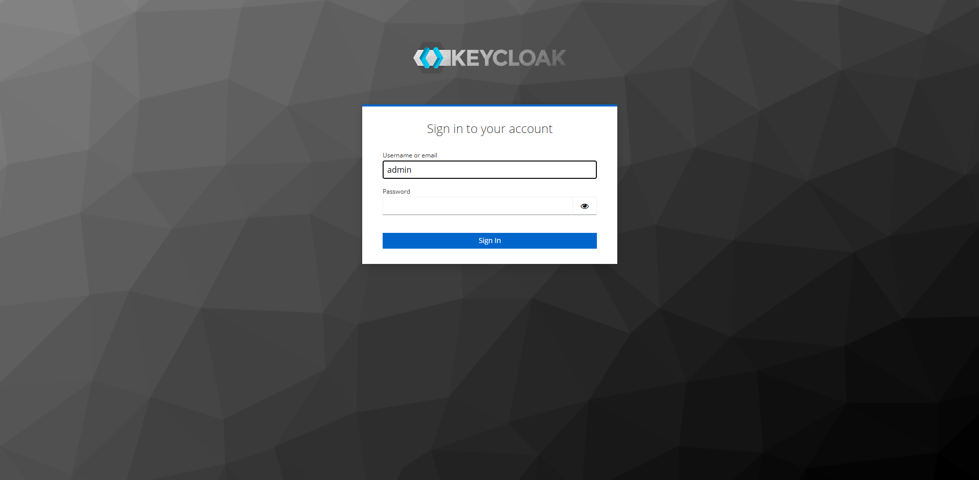
Access the Keycloak Admin console at https://localhost:5010.
Use the default username as admin with the keycloak_admin_password value configured in config_install.yml before running the ./edgesoftware install command to successfully login into Keycloak Admin console.
User Creation#
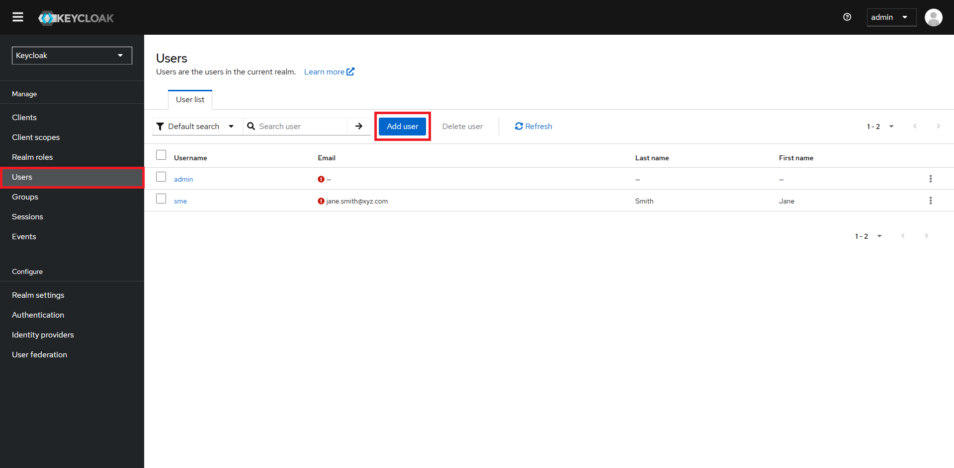
For adding new users:
Navigate to the ‘Users’ section.
Click ‘Add User’.
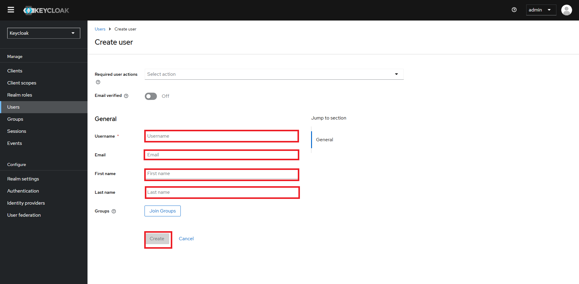
Fill in the user’s information - username, name, email, firstname & lastname.
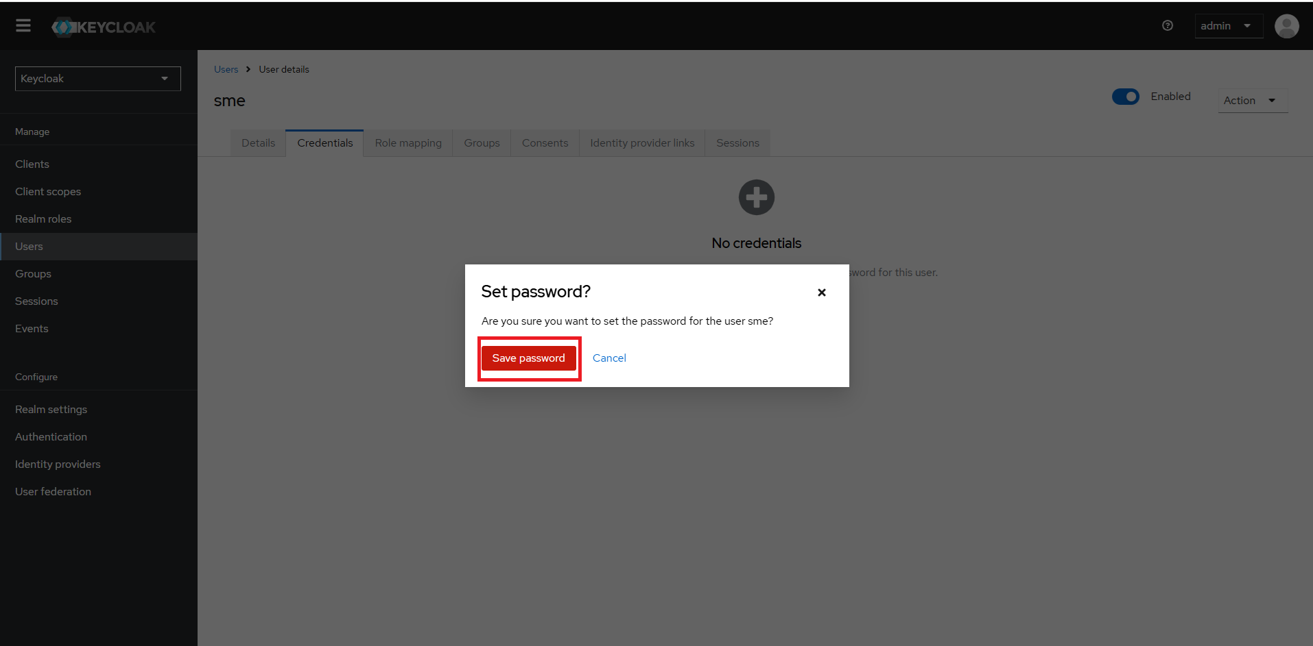
Under the ‘Credentials’ tab, set a password for the user, untoggle the temporary password option and click on Save.
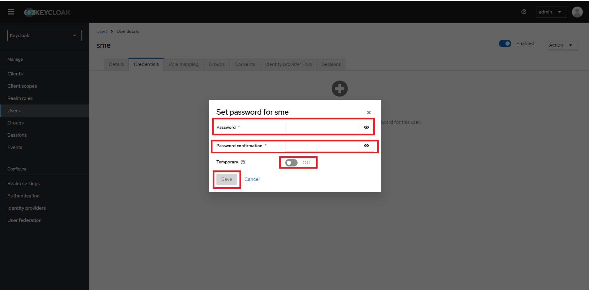
Save password!
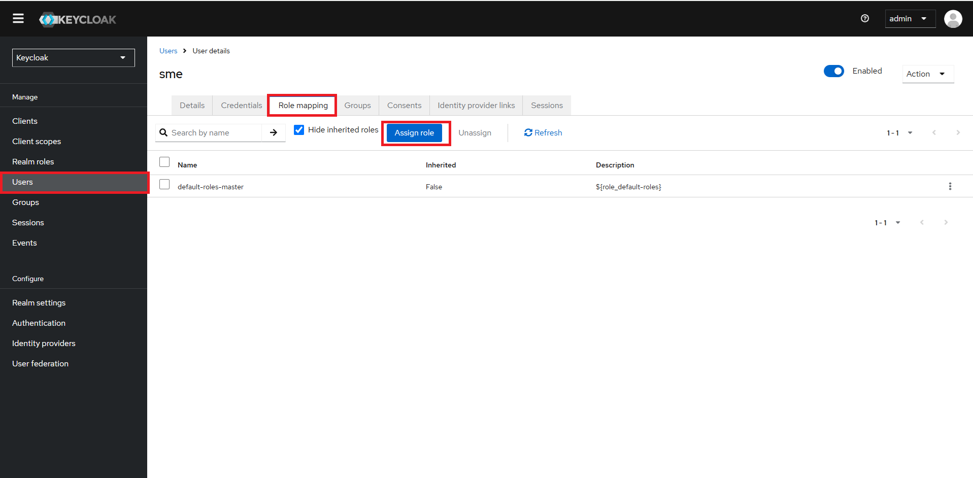
Under the ‘Role mapping’ tab, click on the “Assign role”.
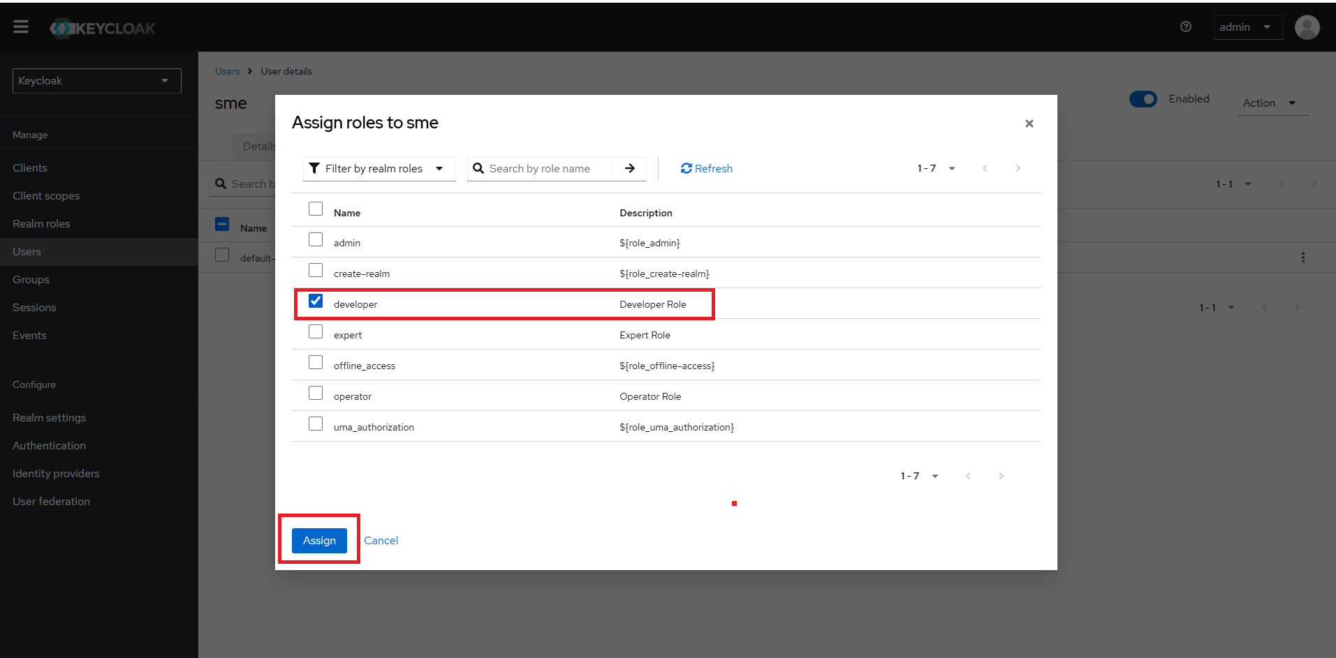
From the dropdown in the top left corner of the pop-up window, select ‘Filter by Realm Roles’. Choose all the roles associated with the client i.e. developer, expert and operator
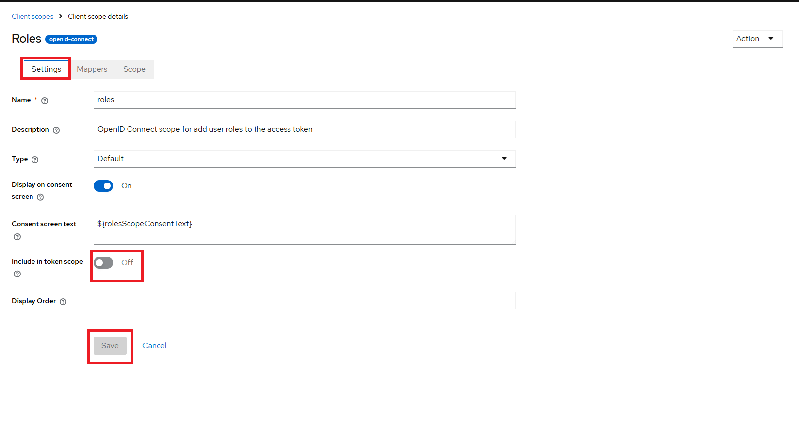
Client Scope Configuration#
To configure client scopes:
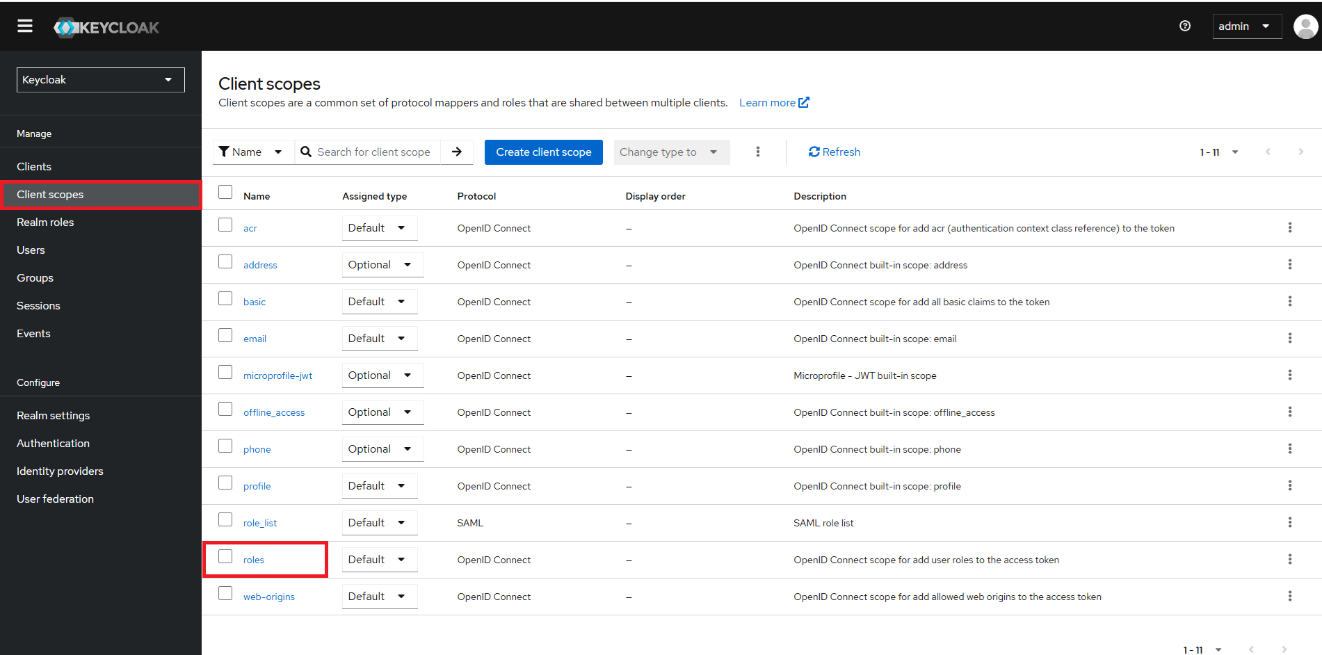
Go to ‘Client Scopes’.
Select ‘roles’.
Click on ‘Settings’ tab.
Scroll down to “Include in token scope” toggle option: toggle it ‘ON’
Note: Sometimes, the
Savebutton may not be enabled. Just click on toggle OFF and ON couple of times to set to ON and see theSavebutton enabled.Click Save.
Now go to ‘Scope’ tab.
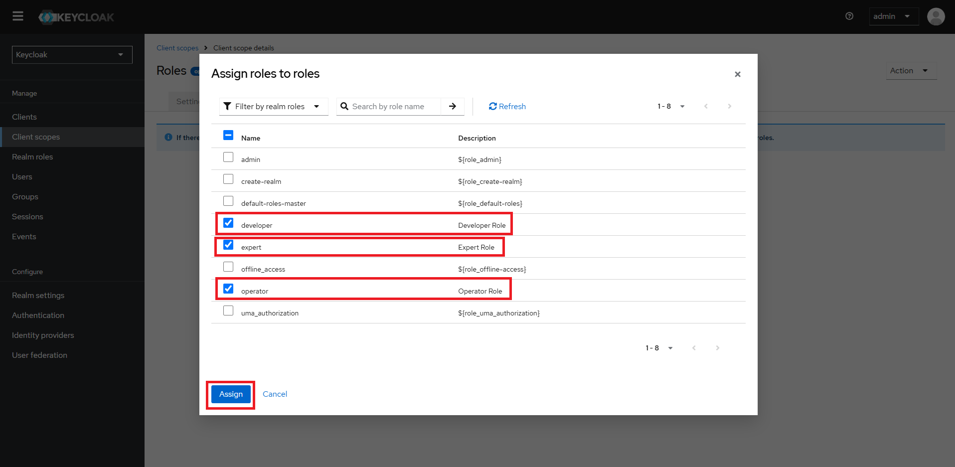
Click on “Assign Roles” button
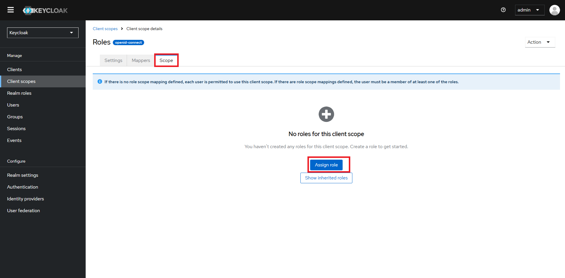
From the dropdown in the top left corner of the pop-up window, select ‘Filter by Realm Roles’. Choose all the roles associated with the client i.e. developer, expert and operator
Role List Configuration#
Go to ‘Client Scopes’.
Select ‘roles-list’.
Click on ‘Settings’ tab.
Scroll down to “Include in token scope” toggle option: toggle it ‘ON’
Note: Sometimes, the
Savebutton may not be enabled. Just click on toggle OFF and ON couple of times to set to ON and see theSavebutton enabled.Click Save.
Now go to ‘Scope’ tab.
Click on “Assign Roles” button
From the dropdown in the top left corner of the pop-up window, select ‘Filter by Realm Roles’. Choose all the roles associated with the client i.e. developer, expert and operator
*Please do the same like “Client Scope Configuration”
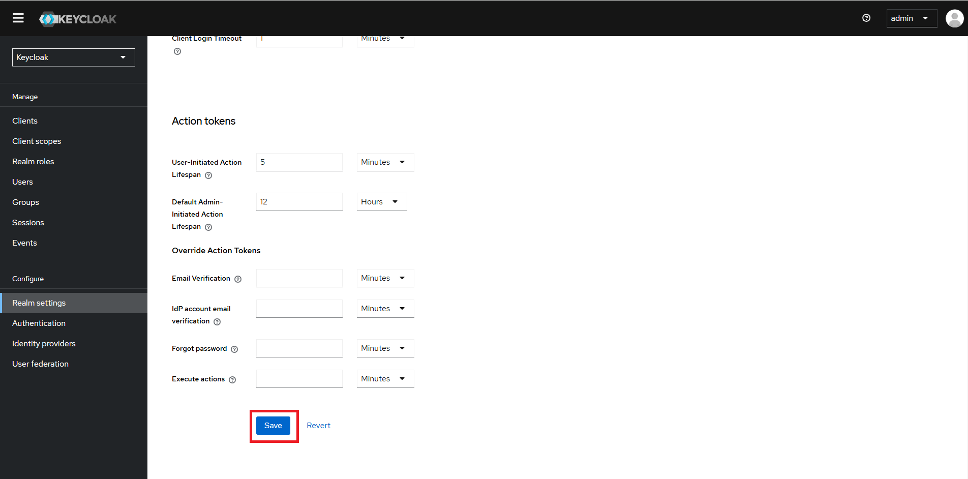
Update Default Signature Algorithm#
Go to Realm Settings
Go to Tokens tab
Go to Default Signature Algorithm -> Select “RS512”
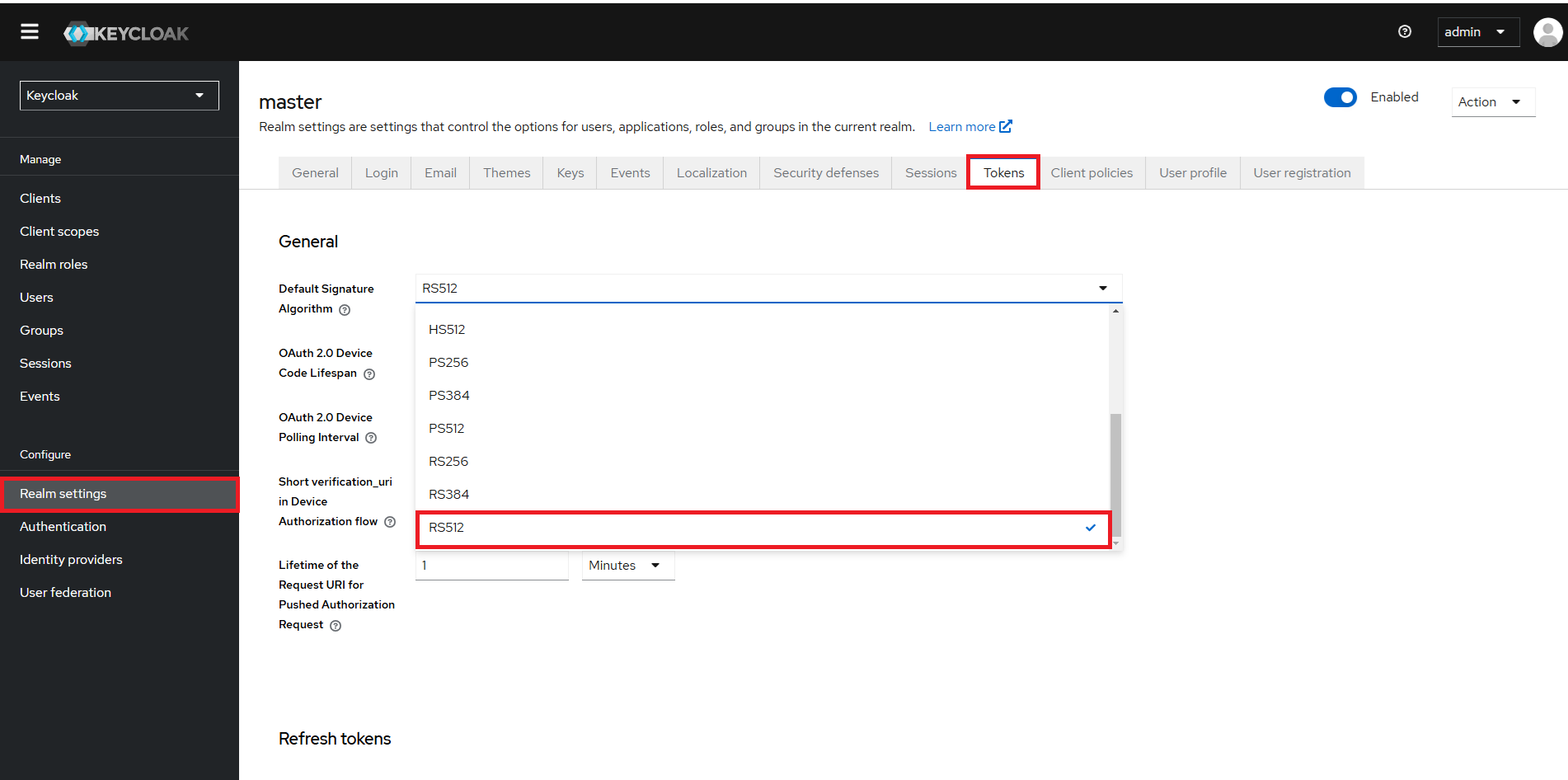
Go to Access tokens -> Access Token Lifespan -> Update the time from default 1 Minute to 5 Minutes
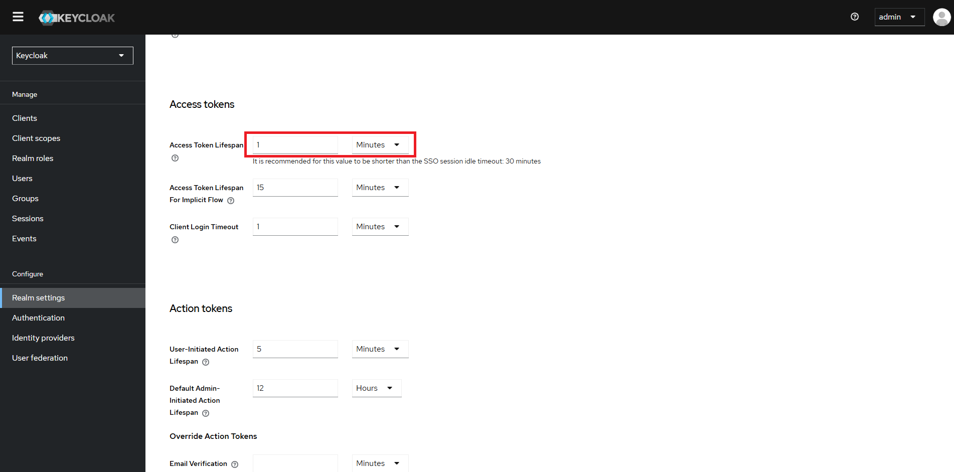
Note: If no user actions are carried out on the WebVision GUI then the user would be forcefully logged out
Click Save
Distributing Credentials#
Securely share the user credential to the intended user(s) you have created. Ensure they securely store this information for future access to the system.
Login#
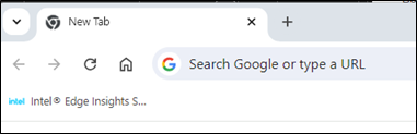
Once the system is powered on, the User must open the web browser (Google* Chrome) to access the Intel® Edge Insights System GUI. Follow the below step to access the Intel® Edge Insights System GUI.
Open the web browser (Google* Chrome) on the system.
Click on the Intel® Edge Insights System GUI that has been bookmarked.
If a bookmark is missing or deleted, then type https://localhost in browser address bar.
Figure 1. Intel® Edge Insights System GUI Bookmarked
Login with the respective credential.
Figure 2. Login Page
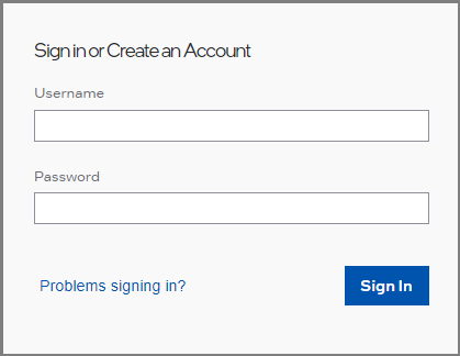
Contact administrator for username and password for developer and operator. t
Developer Login Page#
After logging in as an Developer, the user will be redirected to the dashboard below.
Click Right chevron(right arrow)to see the full menu for navigation on the left panel.
Figure 3. Developer Dashboard without navigation expand
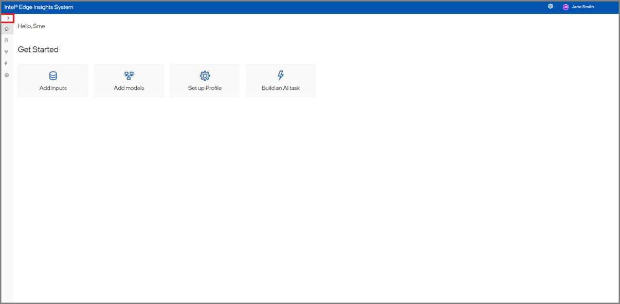
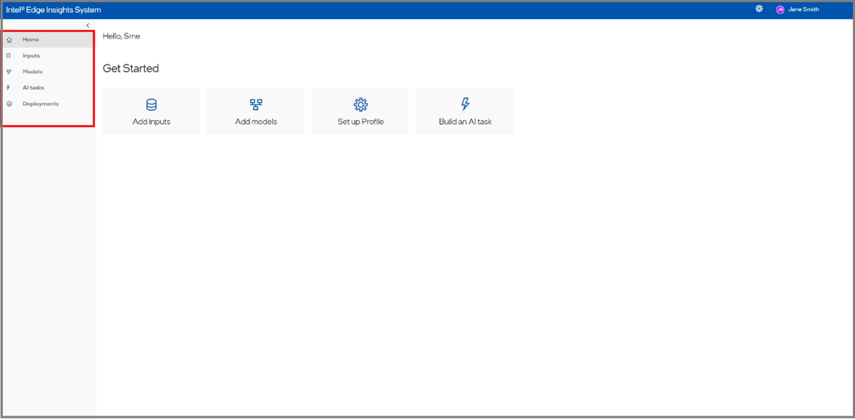
Figure 4.Developer Dashboard with navigation expand
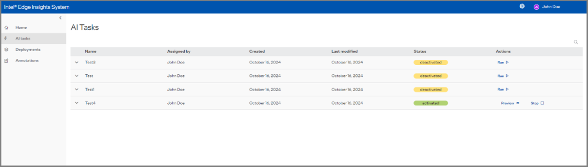
Operator Login Page#
In this section, the operator will be able to see the list of AI Tasks that are configured by the developer.
Figure 5. AI Task list
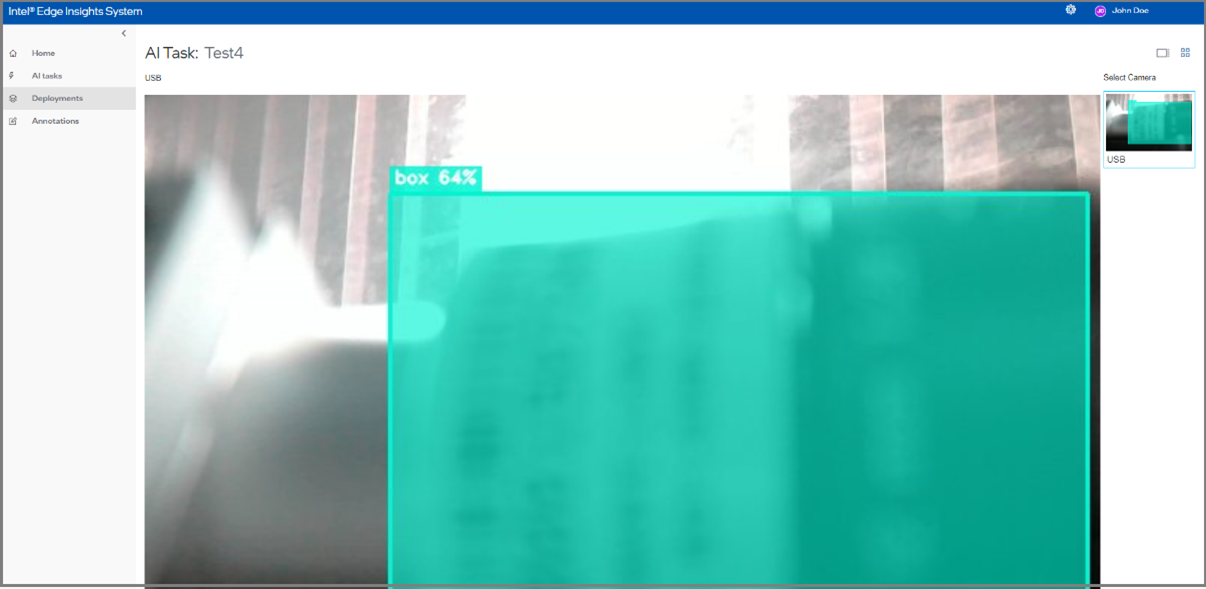
The operator will be able to see the visualization output of the inferencing result based on the configuration use case configured by the developer.
Figure 6. Operator View
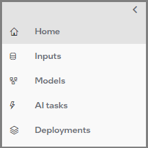
Navigation Menu#
After logging in as an Developer and expanding the navigation menu, the user can see a list of navigation items.
Figure 7. Navigation Menu
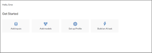
Home#
The Home is like a dashboard for Developer login.
Figure 8. Home
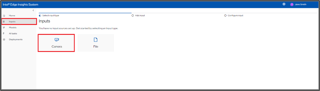
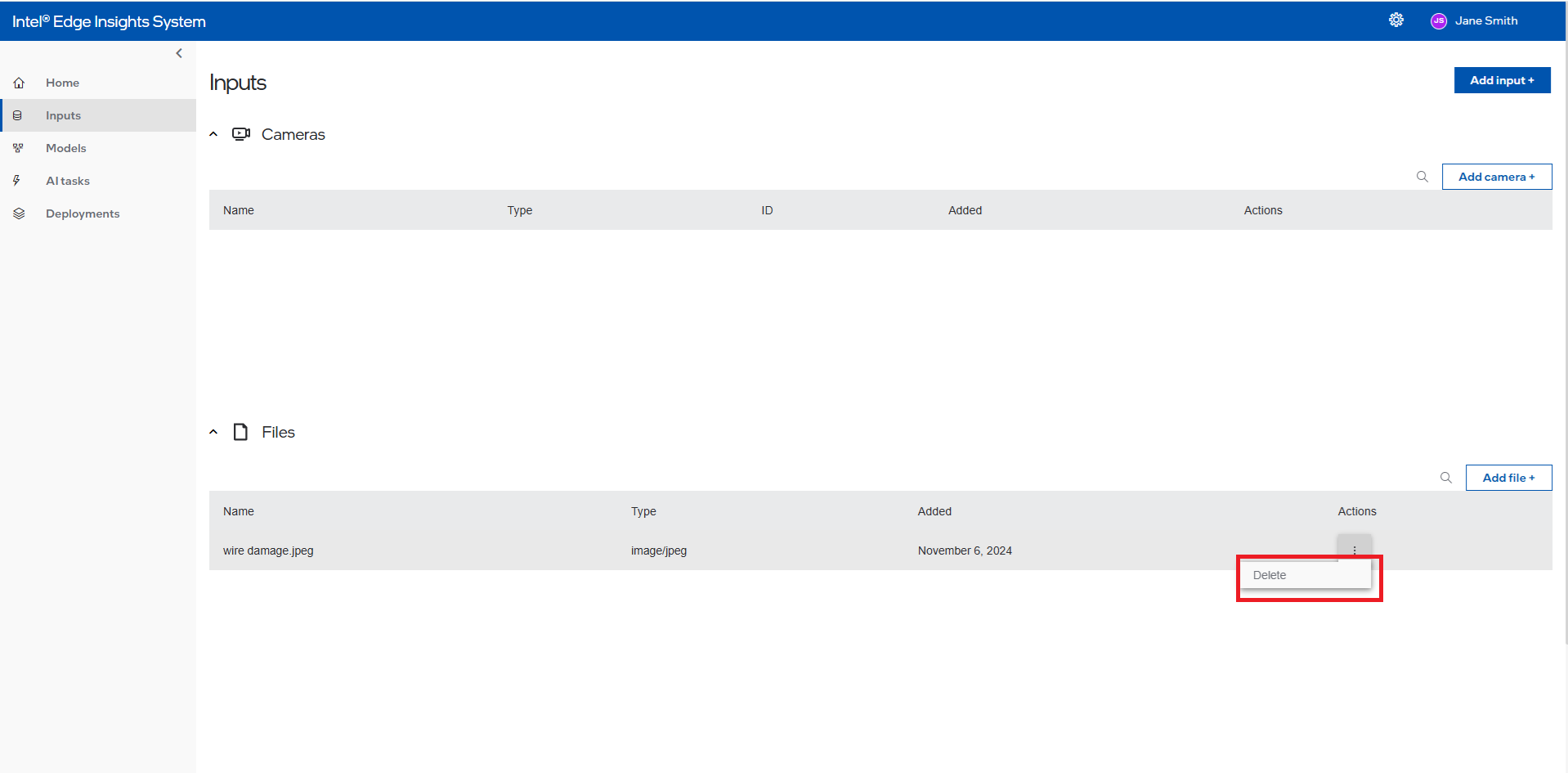
Inputs#
In the Inputs Automation Menu, the User will be able to connect cameras and Files to work with an application and view a summary of the added cameras and Files. Refer to the add new camera section to get the detailed steps to add the camera.
Select the ‘Inputs’ tab in the side navbar to view all connected cameras and files, if any connected cameras and files are there, if not user can add the cameras and files.
Figure 9. List of Inputs
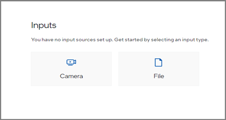
Figure 10. Example of Connected Cameras and Files
List of Supported Cameras and Files#
Shown below are the types of cameras supported by Intel® Edge Insights System.
Figure 11. List of supported cameras
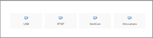
Figure 11List of Supported Files
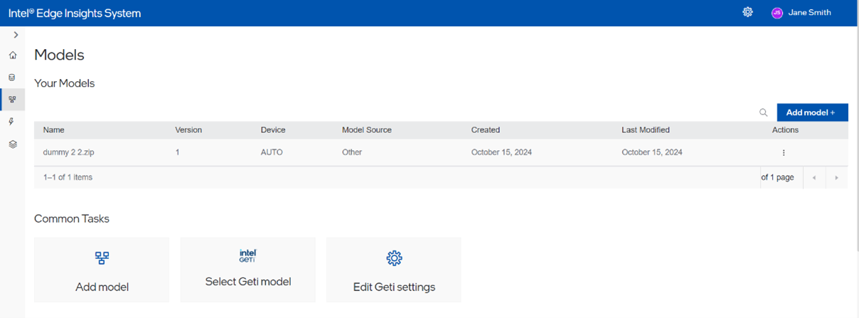
Intel® Geti™ Models#
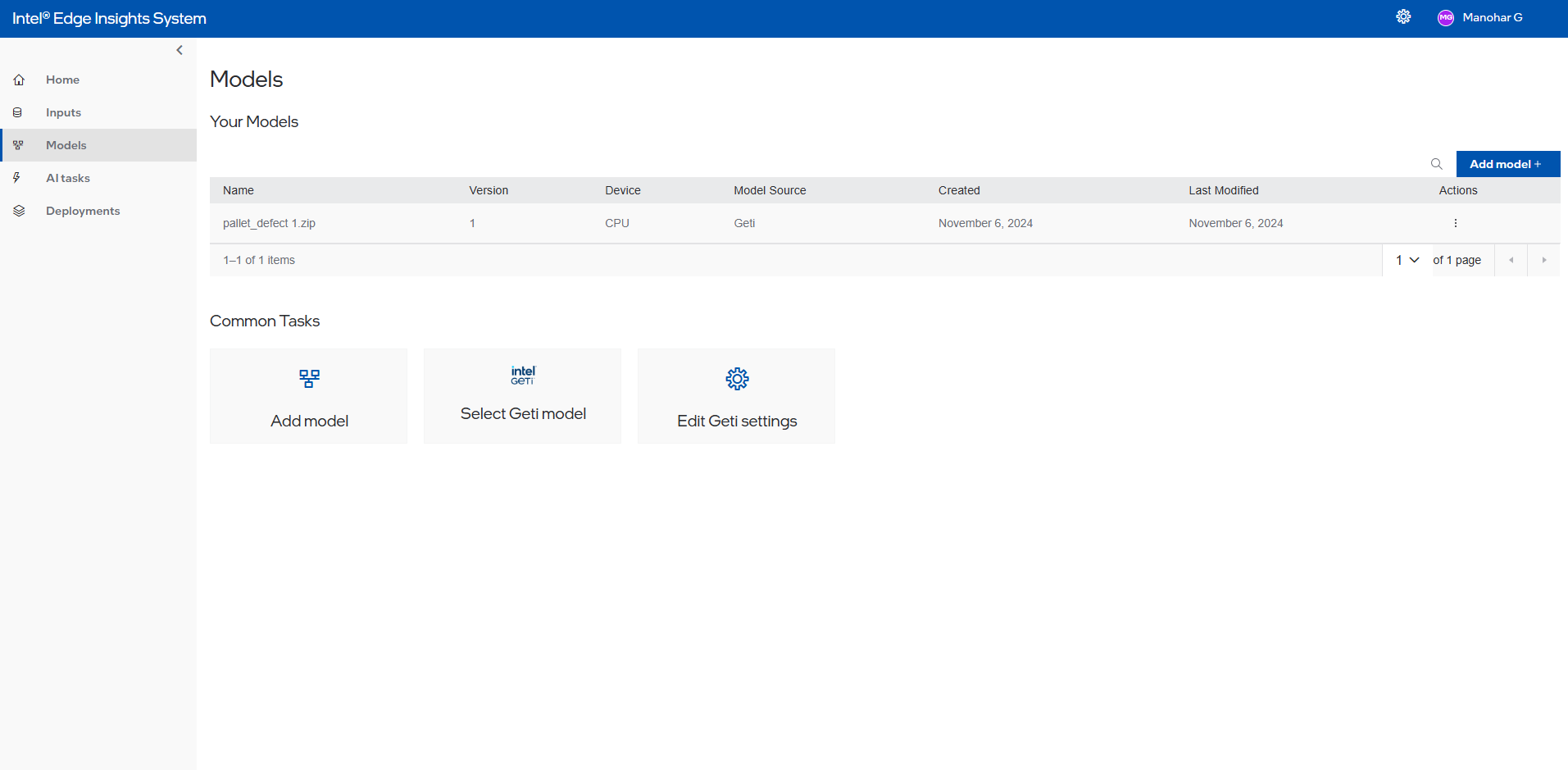
The ‘Models’ tab allows the User to add Custom and Intel® Geti™ Model and model processing file to obtain the expected inferencing output. Refer to the ‘ Add models section to get more details.
Below is an example summary of imported Intel® Geti™ Models.
Figure 9. Intel® Geti™ Models Summary
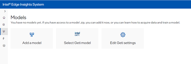
Add Models#
The Models’ tab allows the User to add a custom model and model processing file to obtain the expected inferencing output. Refer the ‘Add Model’ section to get more details.
Below is an example summary of imported Custom Models. Please note that the date fields are in dd/mm/yyyy format.
When user click on add models add models screen is visible as below
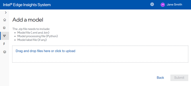
Where user upload file then below screen will be visible where user has to give inputs like version device model source.
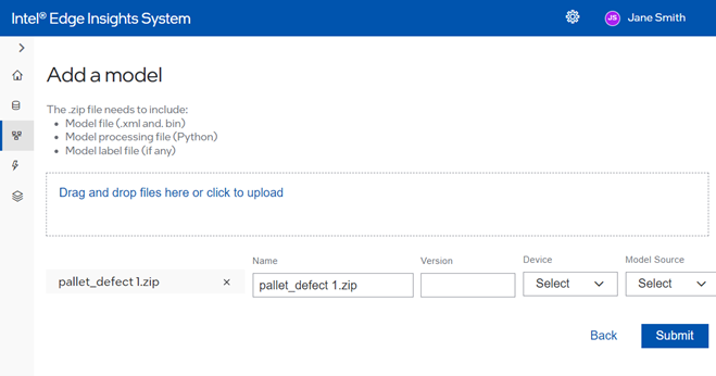
When user click on submit then model will get uploaded to server
And will be listed in list page as below
Figure 10. Custom Models Summary
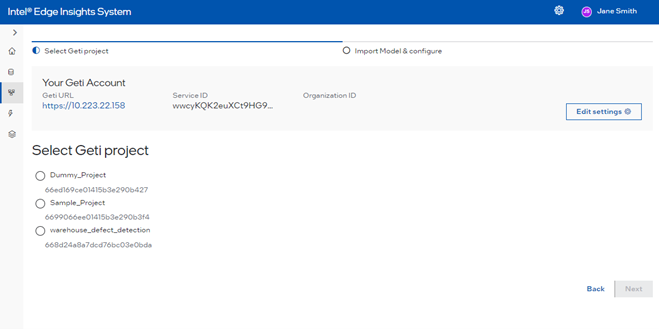
On Select GETI Model
User will see a select project screen where the user can select the project and click on the next button
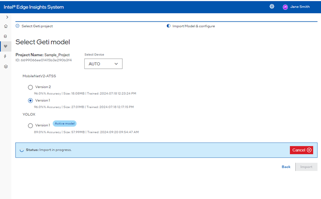
User will see models details
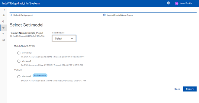
After selecting the model and version select the device then click on import, it will get uploaded
Project#
The ‘Project’ tab allows users to create a new project and configure the end-to-end flow from data ingestion to data analytics and data storage by using the component added to the Intel® Edge Insights System and showing the summary of the added projects. For more details refer Create New Project.
Project Preview#
The ‘Project Preview’ tab allows the user to preview the output of the created project. In this tab, the user can perform following:
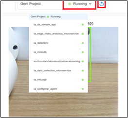
check the project state – the “Running” state if it runs successfully. On drop-down, the status of all internal modules is also listed.
restart the project by using the Restart button.
Figure 11. Project Preview
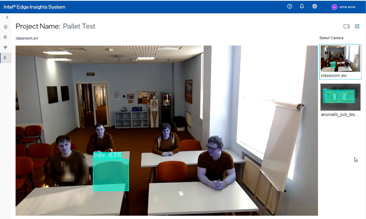
Figure 12. Visualization Output with Names, State, and Restart Button
Annotations – Operator role only#
This used for annotations
When user click on next
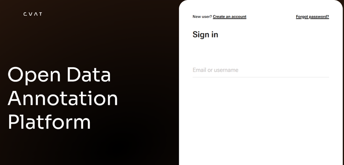
User can see the annotations details on click on Button Go to annotation Tool it will open new window and will ask for login
#
System Settings#
The ‘System Settings tab allows users to change the settings of a deployed project. For more details refer Change System Settings.
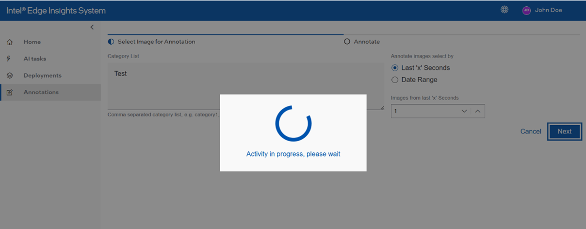
Wait Message#
A “wait message” is displayed when certain tasks are executed in the backend. The wait message disappears once the task is finished.
Figure 13. Wait Message
Add New Camera and File#
This section will cover the steps to add the new camera to be used with the Intel® Edge Insights System.
Follow the below steps to add the new camera.
.
Figure 14. Add the New Camera
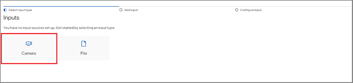
We have two ways to add the cameras:
The user adds the camera the first time, and then the below steps can work.
Click the Inputs and click the Camera button to add the new camera
 2. When the user is added the camera already, then the below page will come, from here also user can add a new camera like the one below
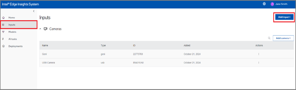
Then click on the camera
Select the desired Camera Type to add.
Figure 15. Select the Camera Type
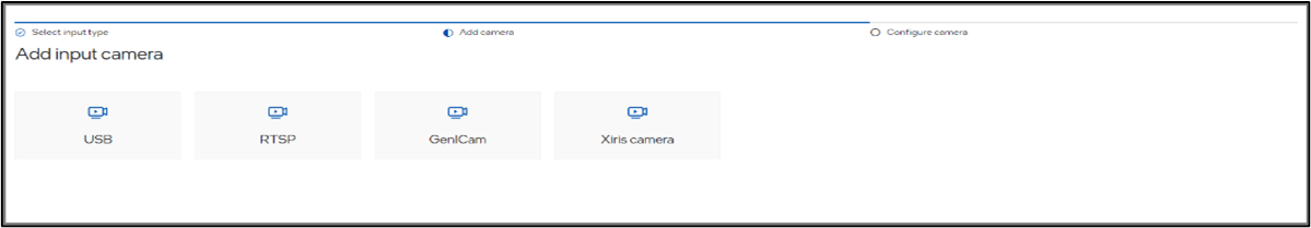
Supported Camera Types#
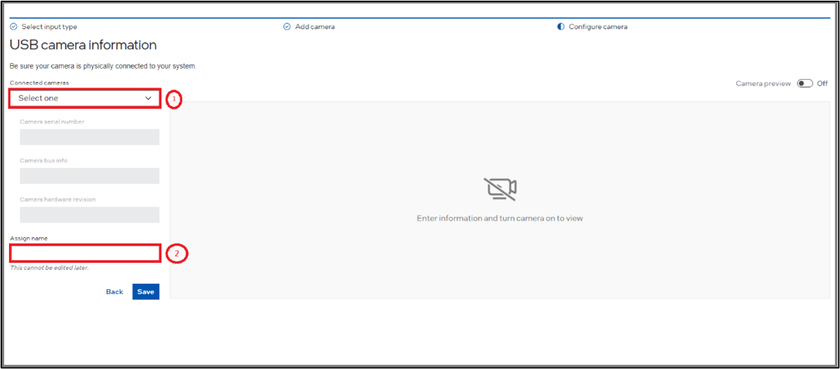
USB Camera#
For USB Camera, select the camera from the Connected Cameras list drop-down menu. The Camera Serial, Camera Bus Info, and Camera Hardware Revision are non-editable fields with the default value based on the selected USB Camera.
Also, assign a camera name (a friendly name) to uniquely identify the camera.
Refer to “Camera Preview” for details of the camera preview toggle button.
Figure 16. USB Camera Selection
RTSP Camera#
The below image is an example of adding the new RTSP camera.
Figure 17. RTSP Camera Selection
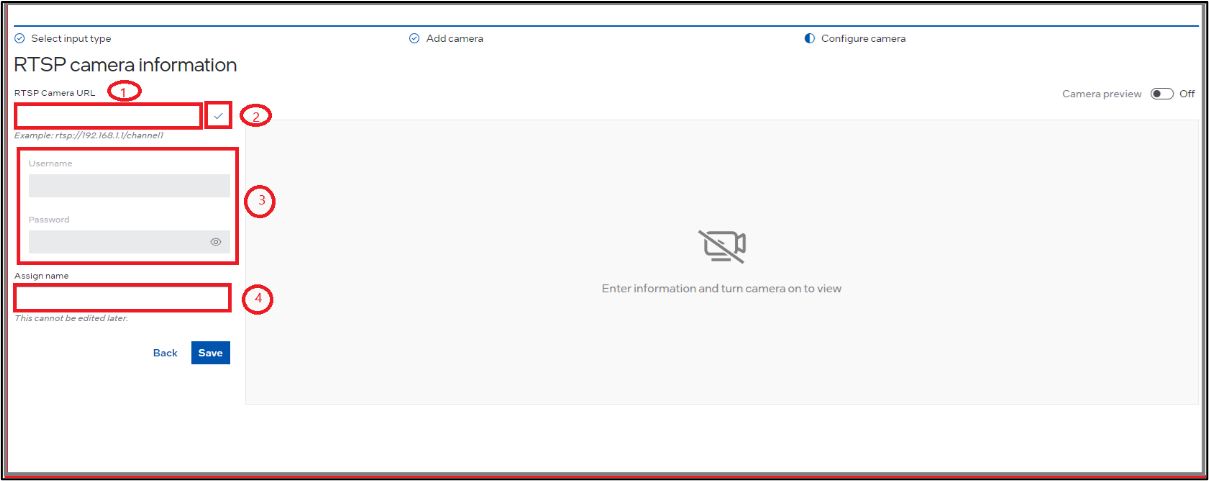
Refer the following steps for adding RTSP camera:
Insert the respective RTSP link (1) in the Camera information section with the respective port example rtsp://192.168.X.X:<port>/main.
After that, click the Search button (2) to verify the connection between the system and the RTSP camera.
Update the username and password (3) for the respective camera in the Camera Details section.
Assign a camera name (a friendly name) (4) to uniquely identify the camera.
After adding the RTSP Camera, the user can edit the username, password for the RTSP Camera.
Refer “Camera Preview” for details of camera preview toggle button.
GenICam Camera#
Note: As a prerquisite, please ensure you have installed the Matrix Vision SDK by following steps mentioned in Edge Video Analytics Microservice docs at https://docs.edgeplatform.intel.com/edge-video-analytics-microservice/user-guide/detailed_usage/camera/genicam.html
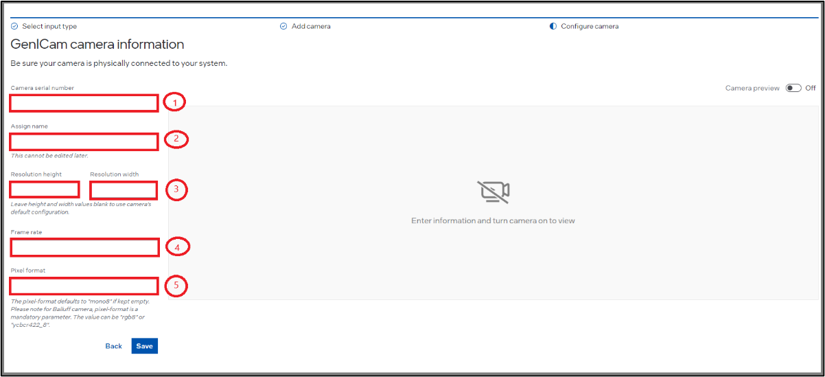
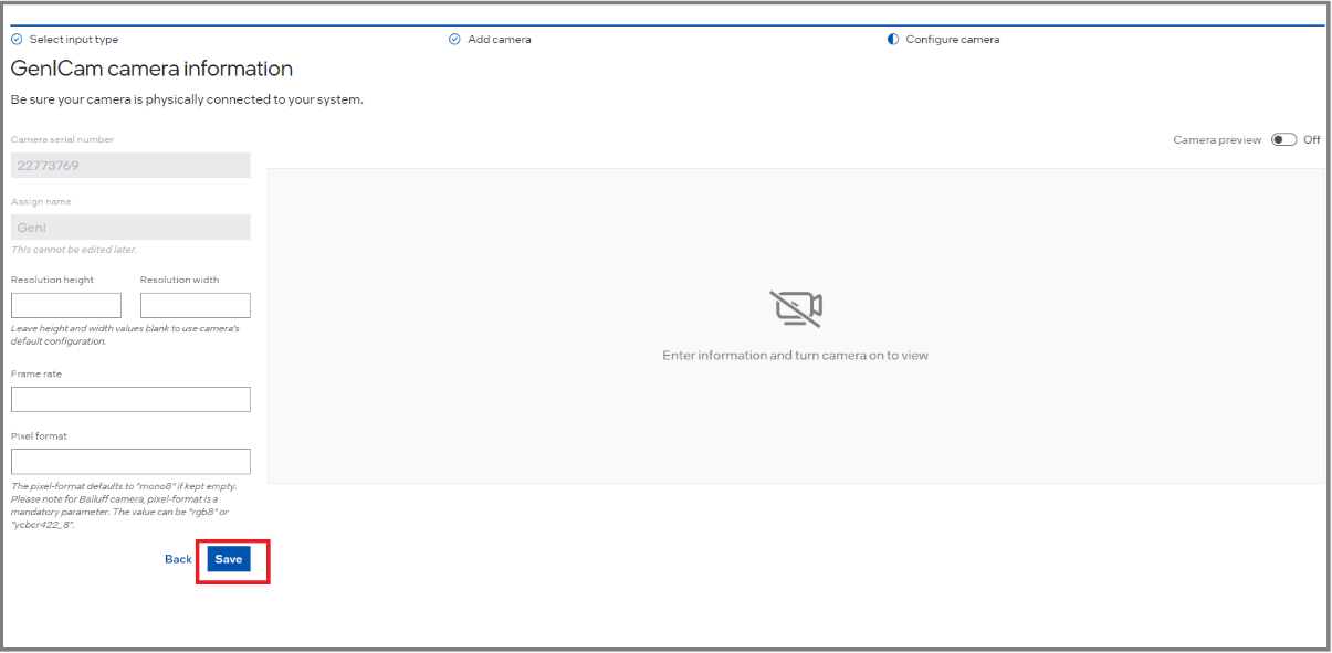
The below image is an example of adding the new GenICam camera.
Assign a camera name (a friendly name) to uniquely identify the camera.
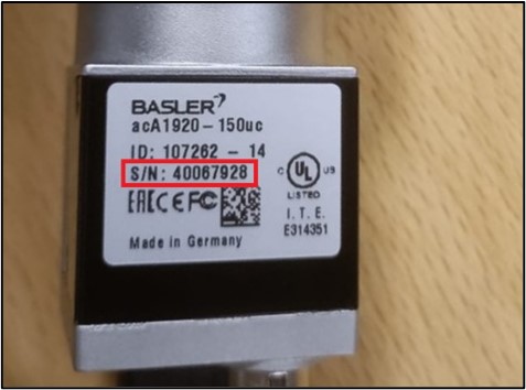
For GenICam, add the camera serial number. Please refer the camera manufacturer guidelines to get the serial number.
For a few cameras, the serial number can be found on the camera.
Figure 18. Serial Number on Camera (e.g. USB Basler Camera)
The user can also change the resolution height and width, if required.
The user can change the framerate to meet the requirements and as per system configuration.
The user can change the pixel format if needed. Default value is “mono8”. Please refer camera manufacturer guidelines for supported pixel formats.
Images will be resized (i.e. downscaled) if resolution is changed to a smaller number than the camera defaults.
The vision pipeline will not work properly if incorrect serial number or pixel format is used as an input.
If camera resolution and frame-rate configurations are kept empty, then the camera defaults will be taken up.
Figure 19. GenICam Camera Selection
Refer “Camera Preview” for details of camera preview toggle button.
Xiris Camera#
The below image is an example of adding the new Xiris camera.
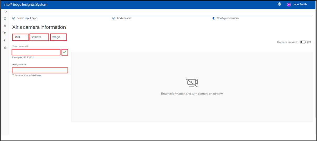
On the Xiris camera page, below the Xiris camera information, there are three tabs: Info, Camera, and Image. Each tab contains several fields.
Info Tab:
By default, the page opens on the Info tab, which has two input fields:
Xiris Camera IP: text input field for the Xiris camera IP.
Assign Name: text input field for the name assignment.
Enter these details and then proceed to the next tab.
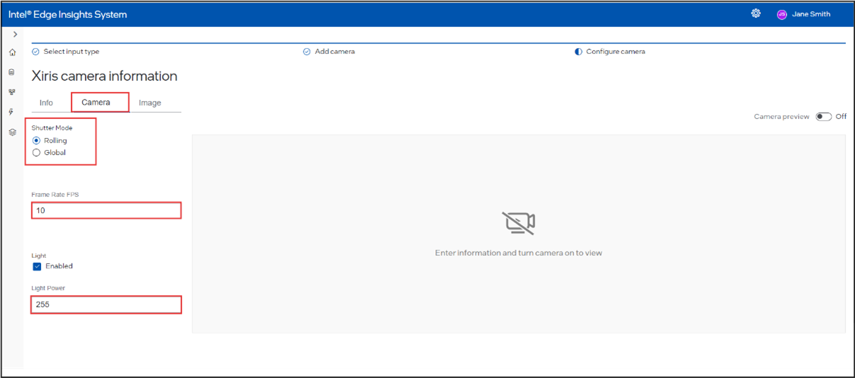
Camera Tab:
This tab includes:
Shutter Mode: a group of radio buttons with options for Rolling and Global.
If Rolling is selected:
Frame Rate (FPS): integer input field.
Light: checkbox.
Light Power: integer input field.
If Global is selected:
Exposure Time (µs): integer input field.
Auto-Exposure Mode: a group of radio buttons with options for Off, Once, and Continuous.
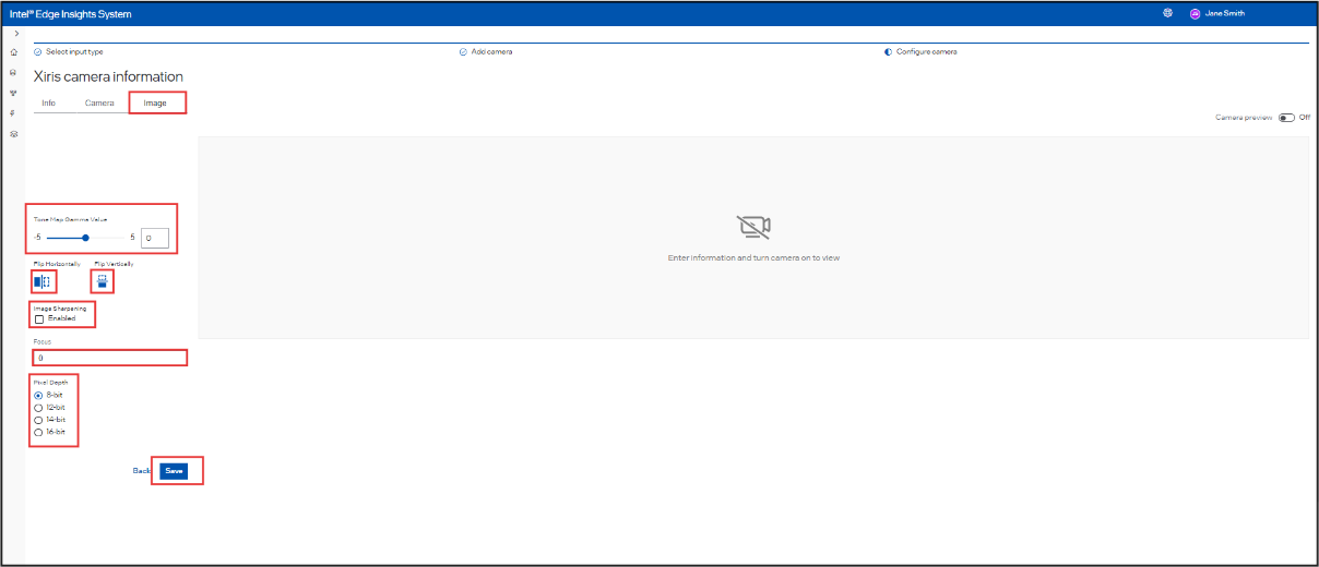
Image Tab:
This tab features:
Tone Map Gamma Value: slider with a range from -5 to 5.
Flip Horizontally and Flip Vertically: icons that can be selected or deselected by clicking.
Image Sharpening: checkbox.
Focus: text input field.
Pixel Depth: a group of radio buttons with options for 8-bit, 12-bit, 14-bit, and 16-bit.
After configuring all the values in each tab, click Save to save the Xiris camera settings with the specified properties.
To find the IP address of the camera, run the LinuxSample application under weldsdk installation directory on the host system. With a default installation, the LinuxSample should be provided under `/opt/xiris/weldsdk/LinuxSample/launch.sh`. The vision pipeline will not work properly if incorrect IP address is used as an input.
Figure 20. Xiris Camera Selection
Refer “Camera Preview” for details of camera preview toggle button.
Camera Preview#
After configuring the camera as required, the user can preview the camera before proceeding to save it. Click the Camera Preview slider to enable the camera preview. A wait message is displayed when camera preview is enabled or disabled.
Below image is an example of a RTSP Camera Preview.
Figure 21. Camera Preview
Click Save button to save the configured camera. Now, you have successfully added the camera to be used with the Intel® Edge Insights System.
Figure 22. Camera Preview – Save Button
For GenICam, to observe the effect of change in configurations (e.g. resolution height/width, pixel-format and frame-rate) on the camera preview, if the camera preview is already running, disable the camera preview and enable it back.
It is recommended to close the camera preview by toggling the button before saving the camera details.
Camera Edit#
After adding the camera successfully, if the user wants to Edit the camera, click on the Edit option which is there in the camera list, and check the below steps to Edit.
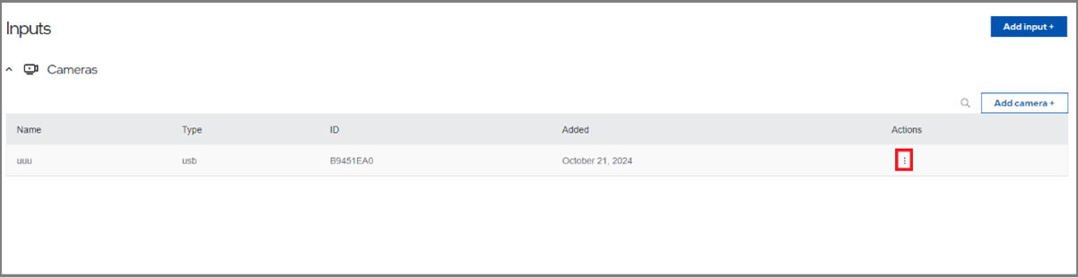
Click on the Edit option
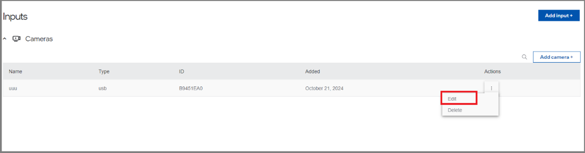
Then the camera registration page will open, user can change the data which is editable.
Then click on the “Save”.
Camera Deletion#
After adding the camera successfully, if the user wants to delete the camera, click on the delete option which is there in the camera list, and check the below steps to delete.
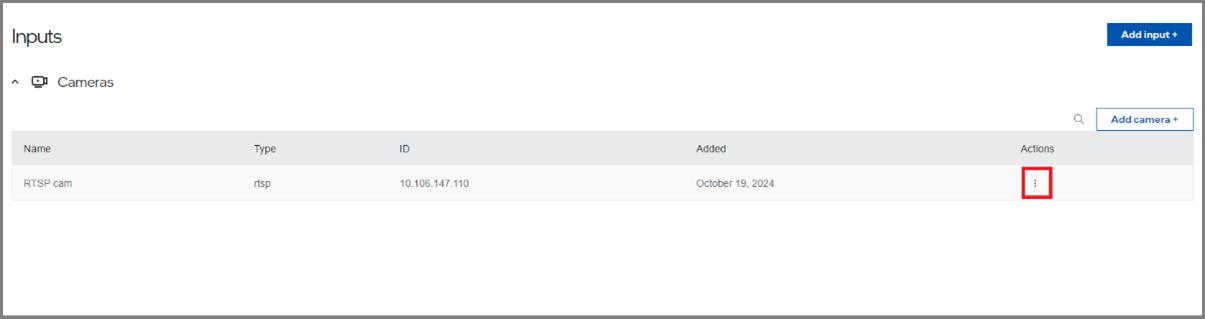
Click on the delete option
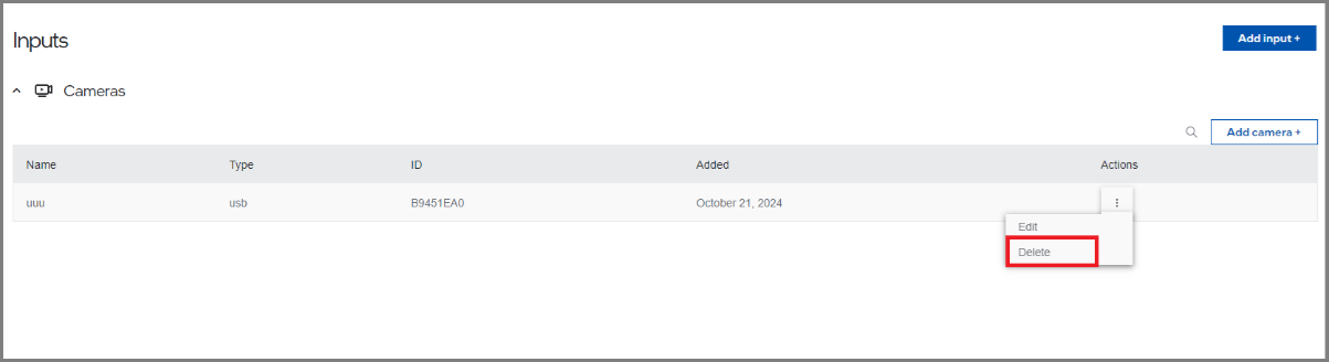
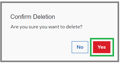
Click on the “yes” to confirm the deletion, then it will get delete from the table.
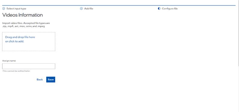
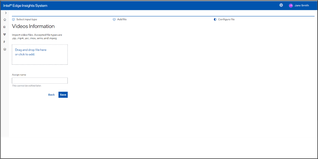
Videos Information#
Click on the left navigation panel and select Inputs from the list of items. The Inputs screen will open. If you have already added any camera or file inputs, a list table will be displayed. To add a new file as an input, click on Add File + to open the Add Input File page.
This will open the Add Input File screen, where you have two options: Image and Video. Click on the appropriate box or tile to proceed to the screen for adding a particular image or video as a file input.
On the Camera or Video File page, either drag the appropriate supported file extensions into the drag box or click on the drag box to open the browse option. Select the required file. The selected file’s name will be updated in the Assign Name input box. You can rename it if desired. Click Save to upload the file.
Supported valid extensions for video files. Accepted file types are .zip, .mp4, .avi, .mov, .wmv, and .mpeg.
Add New Intel® Geti™ Model#
This section will cover adding New Intel® Geti™ Model based on the customer’s specific use case and importing it to Intel® Edge Insights System.
Follow the below steps to add Intel® Geti™ Model to the Intel® Edge Insights System.
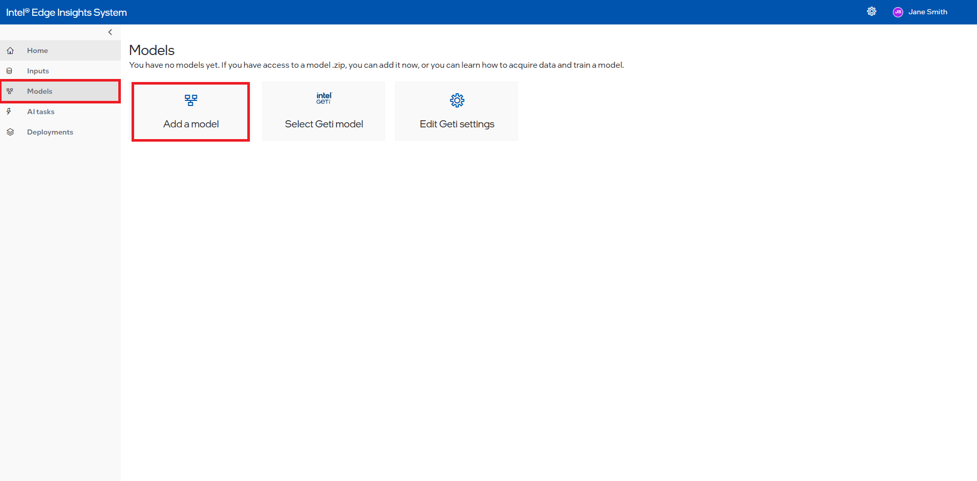
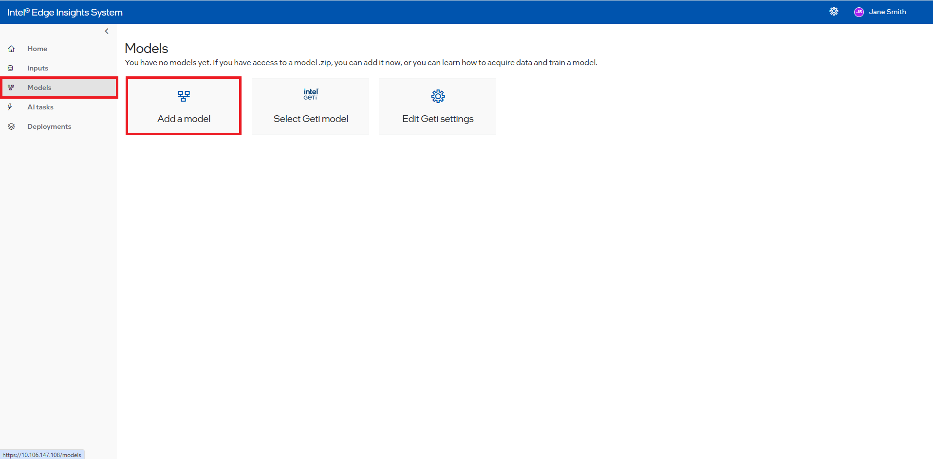
Click Models and Add model button.
Figure 23. Create New Intel® Geti™ Model
Type the model’s Name (1) and click appeared typed name (2) to select the name.
Figure 24. Add Intel® Geti™ Model Name
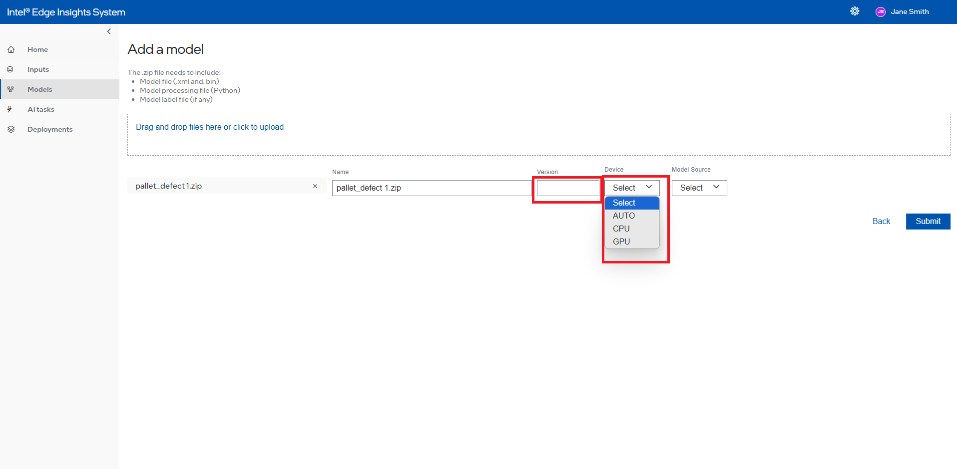
Select device to run the Intel® Geti™ Model. By selecting “AUTO” from the Device dropdown, the application will automatically select the optimal device to run the model. The model will run on the selected device by selecting “CPU” or “iGPU”.
For more information on the Auto selection, refer to the Automatic Device Selection on the OpenVINO™ toolkit website. (https://blog.openvino.ai/blog-posts/automatic-device-selection-and-configuration).
Drop or upload the Intel® Geti Model zip file available from Intel® Geti™ Server.
Figure 25. Drag or Upload the Intel® Geti™ Model
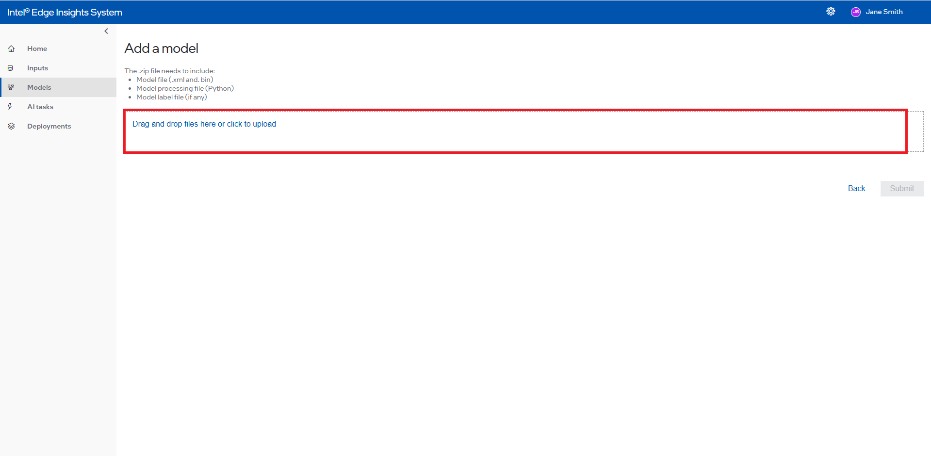
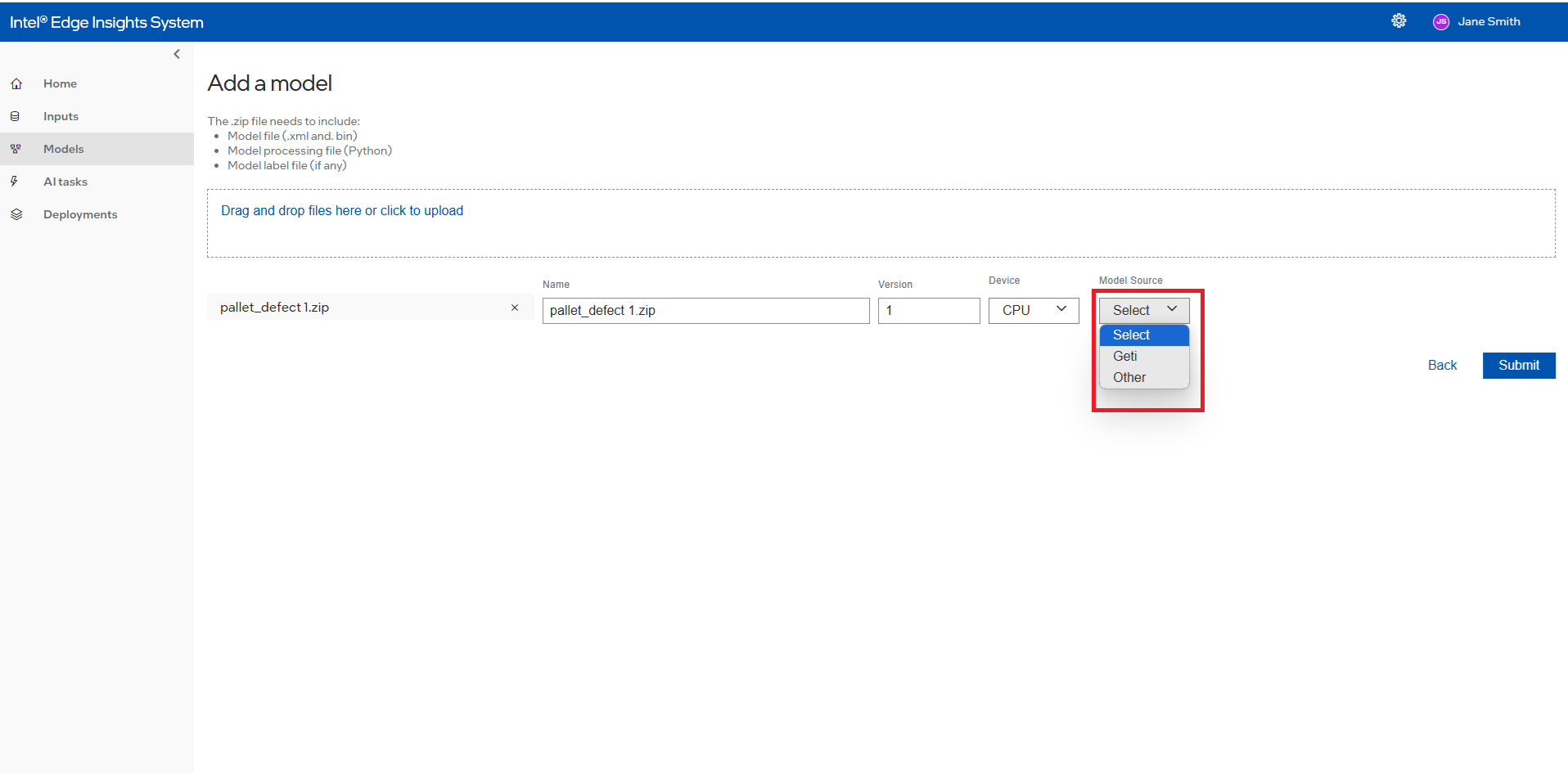
Figure 26. Add the Version and Select Device to Run the Intel® Geti™ Model.
Select the Model Source
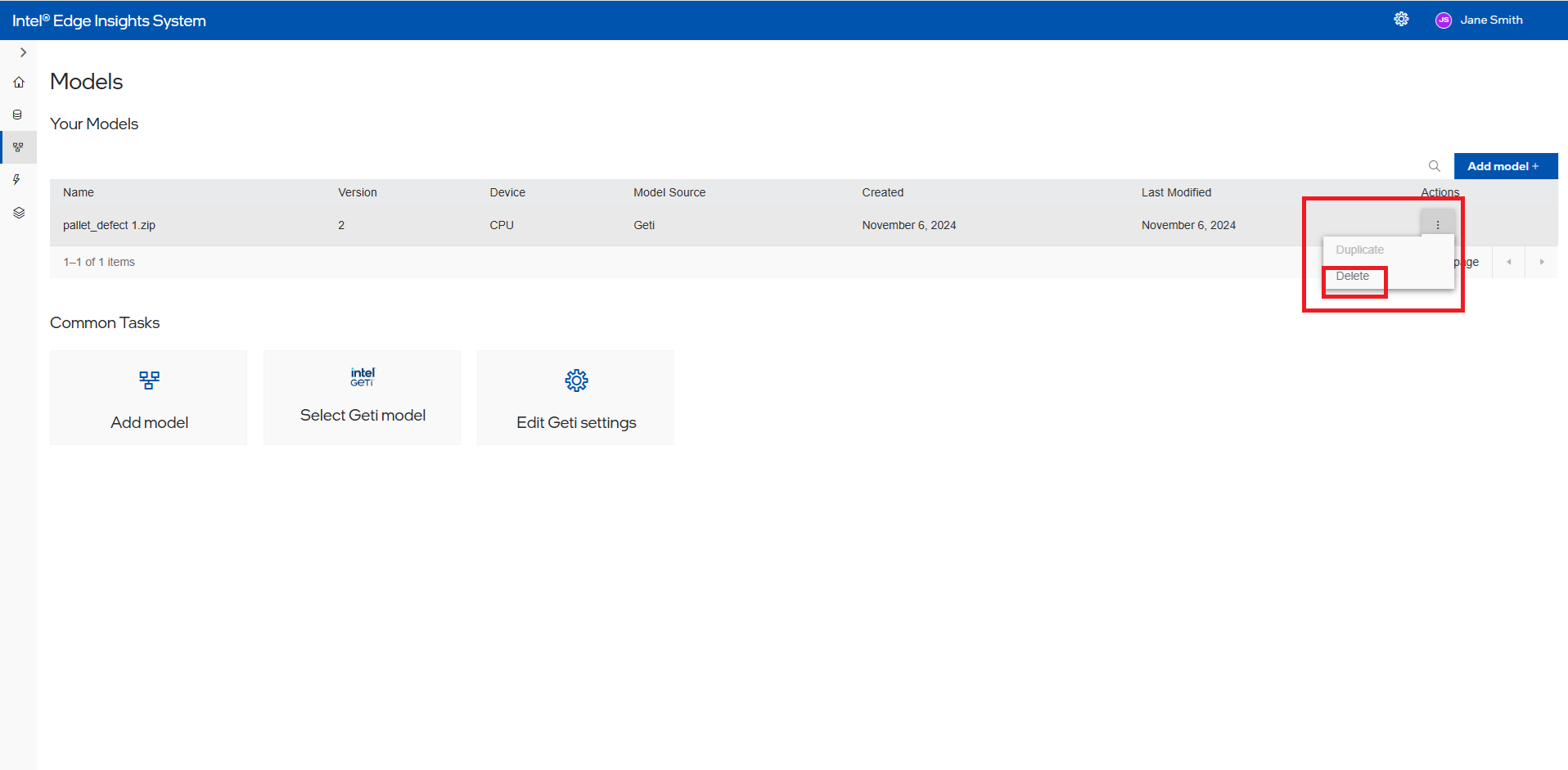
Once completed, the User can see the added model in the Intel® Geti™ model list. Users will be able to delete the custom model added. Please note that the date fields are in dd/mm/yyyy format.
Figure 27. Intel® Geti™ Model Summary Section with Delete Selection
Add New Custom Model#
This section will cover adding New Custom Model based on the customer’s specific use case and importing it to Intel® Edge Insights System.
Follow the below steps to add Custom Model to the Intel® Edge Insights System. For creating your own Custom Model, refer Section “create a new model processing file”.
Click Models and Add model button.
Figure 28. Create New Custom Model
Type the model’s Name (1) and click appeared typed name (2) to select the name.
Figure 29. Drag or Upload the custom Model

Select device to run the custom model. By selecting “AUTO” from the Device dropdown, the application will automatically select the optimal device to run the model. The model will run on the selected device by selecting “CPU” or “iGPU”.
For more information on the Auto selection, refer to the Automatic Device Selection on the OpenVINO™ toolkit website. (https://blog.openvino.ai/blog-posts/automatic-device-selection-and-configuration).
Figure 30. Version Select Device to Run the Custom Model
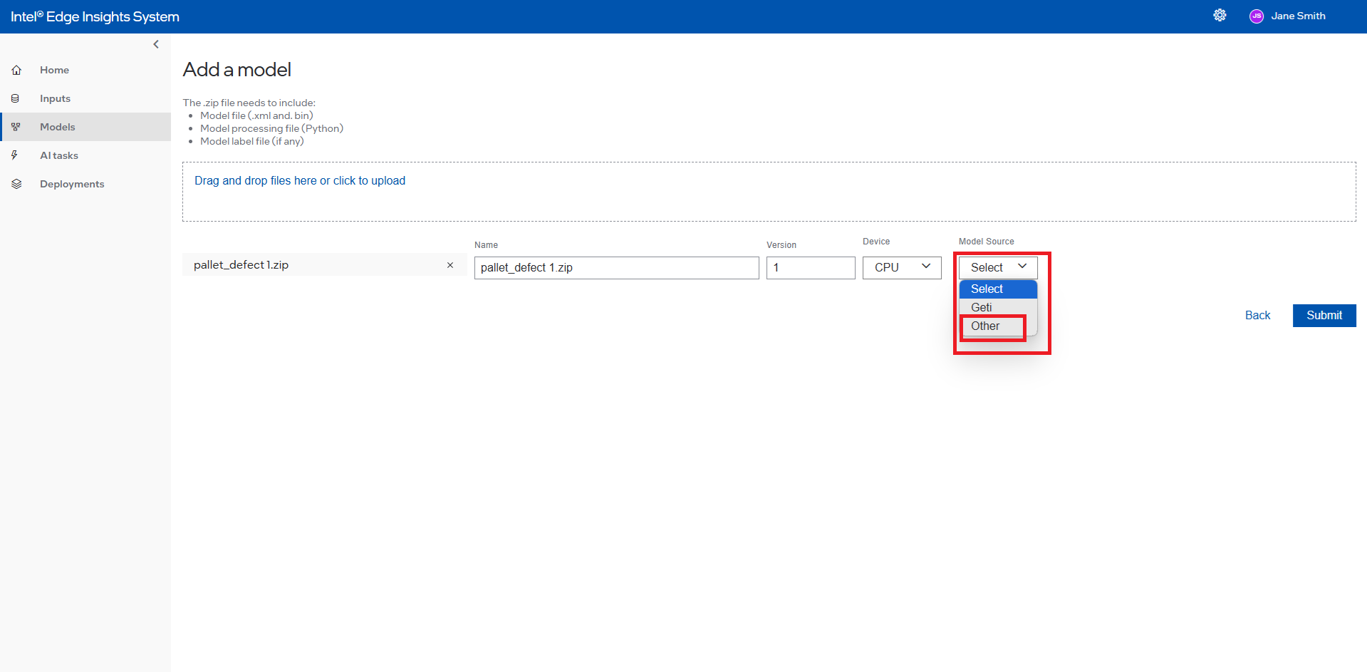
Select the Model Source
For more details on creating the new model processing file, refer Create a new Model Processing File.
Once completed, the User can see the added model in the custom model list. Users will be able to delete the custom model added. Please note that the date fields are in dd/mm/yyyy format.
Figure 32. Custom Model Summary Section with Edit and Delete Selection
Model Summary Section with Delete Selection
Create New AI TASK#
This section will cover the detailed steps for creating a AI Task in Intel® Edge Insights System. The AI Task will consist of selecting the input type (camera/hardware or video file), Processing (models), and output (live or stored video, photos or data files) visualization of the result.
Follow below steps to create new AI Task.
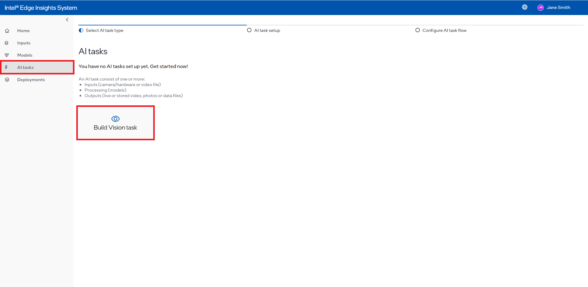
AI Task Information#
On the left navigation panel of menu items, click AI Tasks and an AI Tasks screen will open. On that page, click Build Vision Task.
Figure 33. Create New AI Task
Fill up the Task name and Task description accordingly.
Figure 34. Add Task Name and Task Description
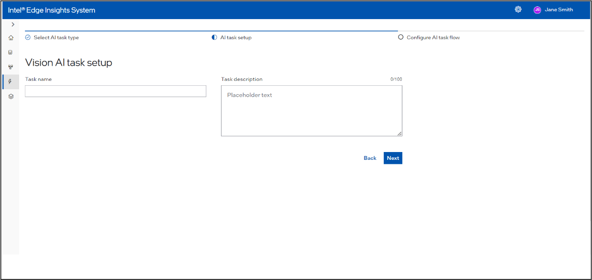
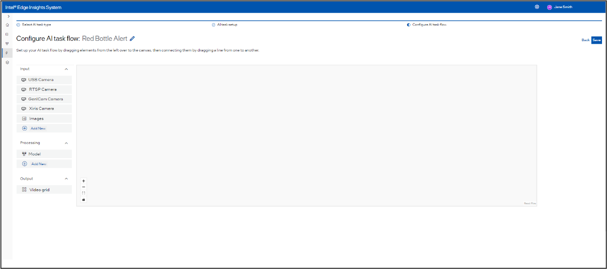
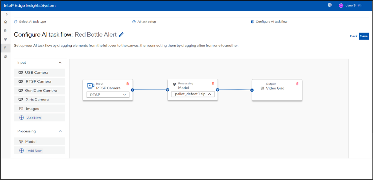
After entering the AI Task name and description (note that entering the AI Task name is mandatory), click Next. The Configure AI Task Flow screen will appear. This screen includes a left sidebar with inputs, models, and outputs nodes, as well as a canvas where you can drag these nodes, connect edges, and create a pipeline Figure 35. Select the Project Pipeline
There are 3 components in a pipeline: input, Processing, output. These components are available in the form of drag and drop nodes. The user can drag, drop and connect these nodes in the canvas as below. Below is an example of the complete end-to-end flow using a GenICam Camera and Intel® Geti™ model with one output.
Figure 42. Pipeline Sample
Input#
Figure 43. Input Selection
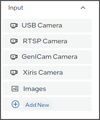
Following types are inputs are supported: Camera and File Input.
Camera#
Supported types of cameras are available under Input. The user should have added the respective cameras (see section – Add New ). The added camera will be available as a drop-down under the camera specific node.
Figure 44. Input Camera Selection (e.g. RTSP Camera)
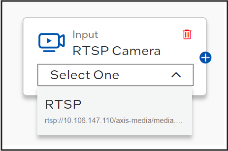
Camera name is displayed in camera listing.
File Input#
Figure 45. File Ingestion
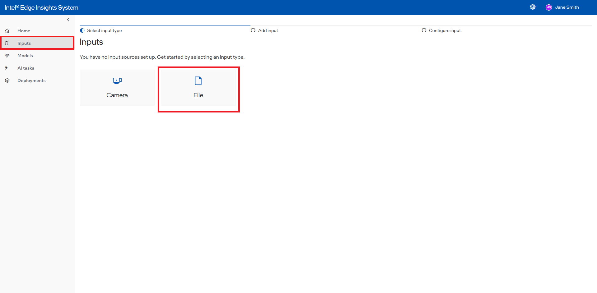
Click on the left navigation panel and select Inputs from the list of items. The Inputs screen will open, allowing you to select either a camera or a file.
If you have already added any camera or file inputs, a list table will be displayed. Click on Add Camera + or Add File + to open the same page as the Inputs page.
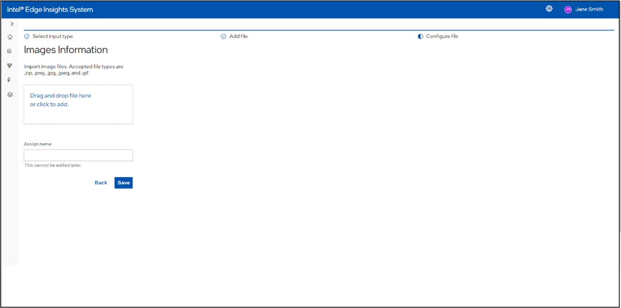
Since we want to add a file, click on File. This will open the Add Input File screen, where you have two options: Image and Video.
Click on the appropriate box or tile to proceed to the screen for adding a particular image or video as a file input.
On the Camera or Video File page, either drag the appropriate supported file into the drag box or click on the drag box to open the browse option. Select the required file.
The selected file’s name will be updated in the Assign Name input box. You can rename it if desired. Click Save to upload the file.
When you drag the input file node to the canvas, it will display the submitted files.
Supported valid extensions for image files: Import image files. Accepted file types are .zip, .png, .jpg, .jpeg, and .gif.
Supported valid extensions for video files: Import video files. Accepted file types are .zip, .mp4, .avi, .mov, .wmv, and .mpeg.
If there are multiple image files in the zip file, then file should be named as: frame_000.jpg, frame_001.jpg, etc.
If there are multiple video files in the zip file, then file should be named as: video_000.avi, video_001.avi, etc.
File name should not have any spaces or special characters like ‘(‘, ‘)’.
The zipped file should not contain a sub folder.
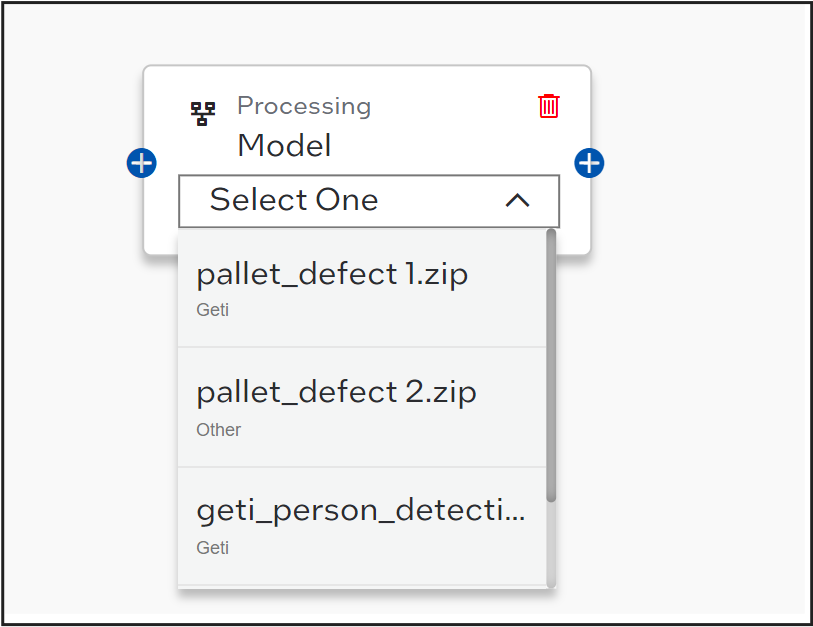
Processing#
Users can drag, drop, and connect one of the supported Processing nodes - Intel® Geti™ Model . The user can select a model from drop-down, provided the respective models are already added.
Figure 46. Model Automation Selection
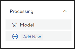
Users can drag these processing nodes onto the canvas. In the dropdown menu of the node, the added models will be available for selection to include in the pipeline. If no model has been added previously, users can click on Add New, which will navigate to the Models screen where a new model can be added.
Figure 47. Model Processing Selection (E.g. Intel® Geti™ Model)
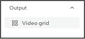
Output#
Users can drag, drop, and connect the output template node.
Figure 48. Template Output Selection
Summary of AI Task Creation Process :#
Click on the Left Navigation Panel and select AI Tasks. The AI Task screen will appear. If there are already AI tasks added, an AI task list table will be shown. To add a new AI task, click on the Add Task + button.
This will open the Vision AI Task Setup where you need to enter the AI Task name (mandatory) and description. Upon clicking Next, you will be taken to the Configure AI Task Flow page.
On the Configure AI Task Flow page, you will see a left side panel with input nodes, processing nodes, and output nodes. You need to create a pipeline by dragging one input node, one processing node, and one output node.
For one AI task creation, you can have a maximum of 4 pipelines.
Before saving the AI task and creating the pipeline, you need to drag at least one input node, one processing node, and one output node. You also need to select at least one item from the dropdown of the input node and processing node. These items will be shown in the dropdown. You need to add these inputs and processing nodes first using the above process or by clicking on Add New below each type of node, which will take you to the corresponding page to add the particular type.
Connect the nodes (edges): the input node’s right edge connects to the processing node’s left edge, and the processing node’s right edge connects to the output node’s left edge.
After creating the pipeline, click on Save. The AI task creation will be successful, and a new page, the AI Task Deployment screen, will be displayed. The list table will show the details of the nodes you added for the AI task.
Edit AI Task 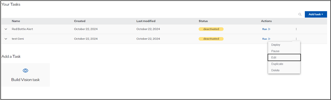 #
#
To edit an AI task by adding a new pipeline or modifying an existing one (by removing or adding any input, processing, or output node in any pipeline), follow these steps:
Click on the overflow menu button and select Edit.
This will take you to the Vision Task Setup screen, where the previously entered name and description will be displayed.
Click Next to proceed to the Configure AI Task Flow screen. Here, you will see the pipeline created earlier.
You can add a new pipeline, delete any particular node (input, processing, or output), and update it with a new one.
Click Save to update the AI task. The updated AI task will be shown on the Deployment screen.
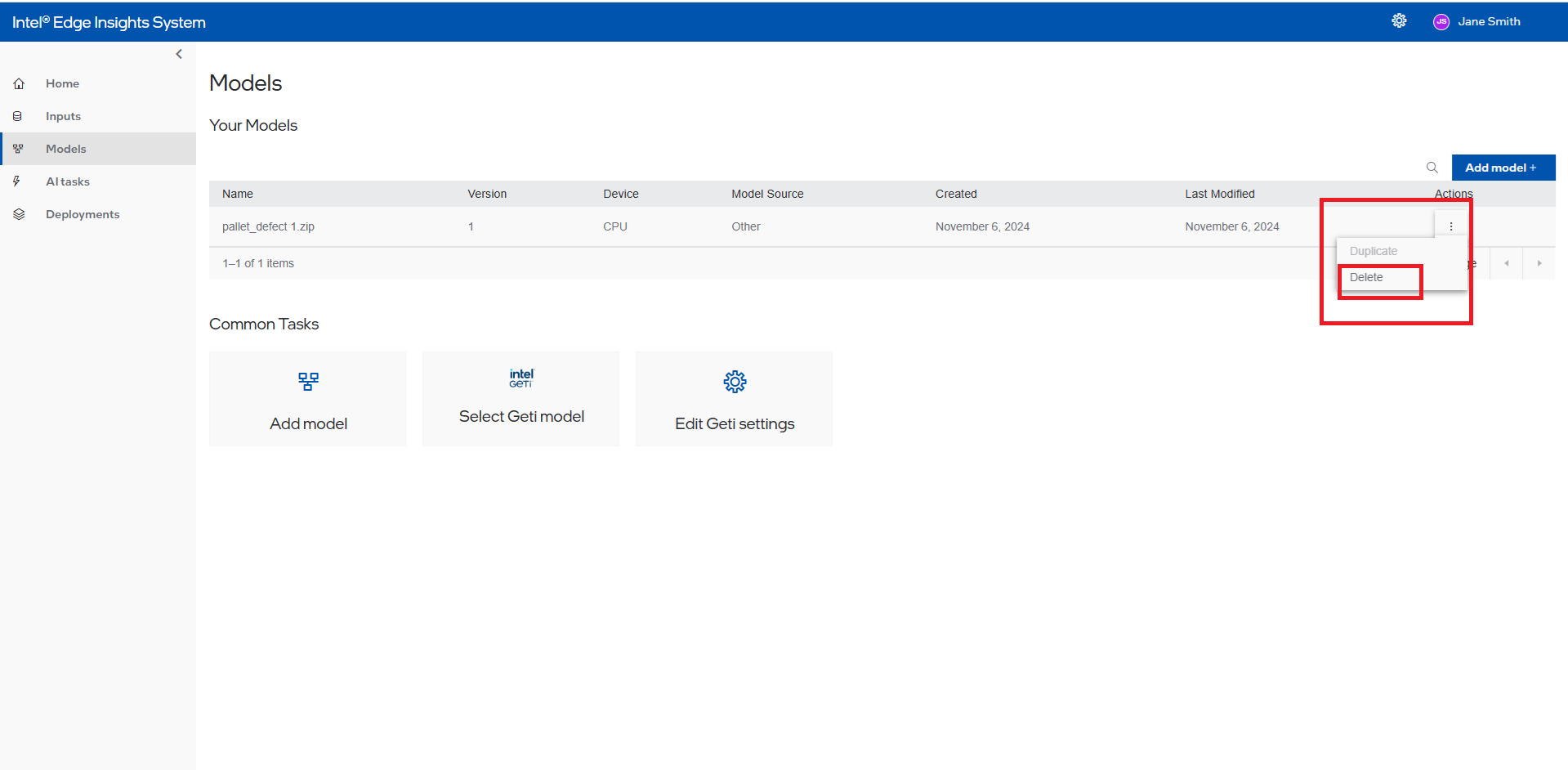
Delete AI Task 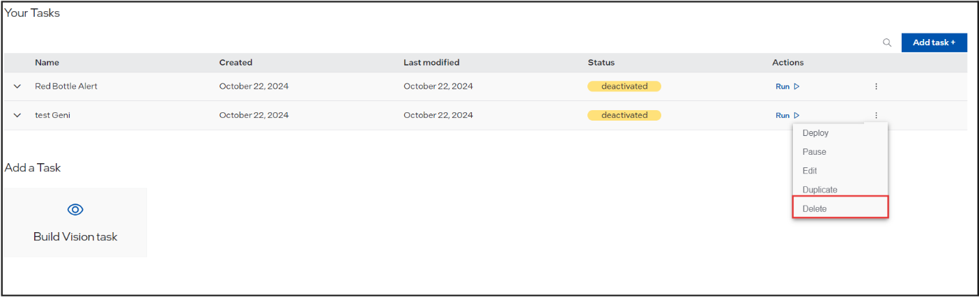 #
#
To delete an AI task, follow these steps:
Click on the overflow menu button.
Select Delete from the menu.
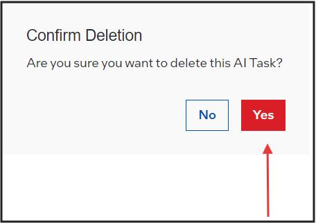
A prompt will appear asking for reconfirmation: “Are you sure you want to delete this AI Task?”
Click Yes to delete the AI task.
AI Task Summary#
Next, the user will see the summary of the newly created AI Task.
Figure 49. Summary of the Created AI Task

Click Run button to activate the created AI Task. A wait message is displayed when AI Task is activated.
Figure 50. Activation AI Task Button

After the AI Task status changes to Activated, click on the Preview section to preview the created template.
Once a AI Task is activated, the user can perform following operations:
Stop the AI Task (deactivate the AI Task). A wait message will be displayed.
View the AI Task pipeline.(In the drop open will show the added input, processing and output node details)
Edit the AI Task: This includes adding a new pipeline, deleting an existing pipeline, or adding/editing nodes within the pipeline.
Delete the AI Task.
AI Task Preview#
Figure 52. AI Task Preview Section
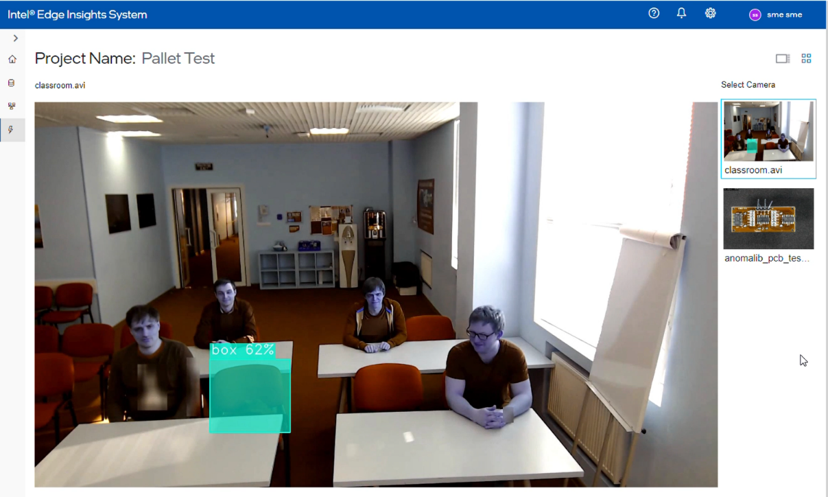
The ‘Project Preview’ tab allows the user to preview the output of the created project. In this tab, the user can perform following:
check the project state – the “Running” state if it runs successfully. On drop-down, the status of all internal modules is also listed.
restart the project by using the Restart button. A wait message is displayed.
The project preview will be visible once complete pipeline is deployed and all modules are up and running. Till then, the user may see messages like “camera off”, “fetching input”, “a refresh icon”, etc. messages may appear. If the images are not auto-loaded after some time, then the refresh of the page using browser can help.
Change System Settings#
The user can change the settings of a deployed project. This section provides the details of settings the user can change. The “System Settings” option will be disabled when no project is deployed.
Settings – Data Retention#
The user can configure the data retention period of the data being stored.
Figure 53. Settings – Data Retention
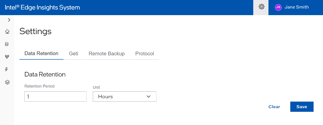
The duration value is a string like “1s”, “1m”, “1h”, “”, “1d”. Here, “s” stands for seconds “h” means hours, “m” means minutes “d” stands days. The default value is 1h and can be changed.
For infinite retention period, use the value as “-1”.
Click on the “save” button to save the changes. This action will restart Datastore container in the backend.
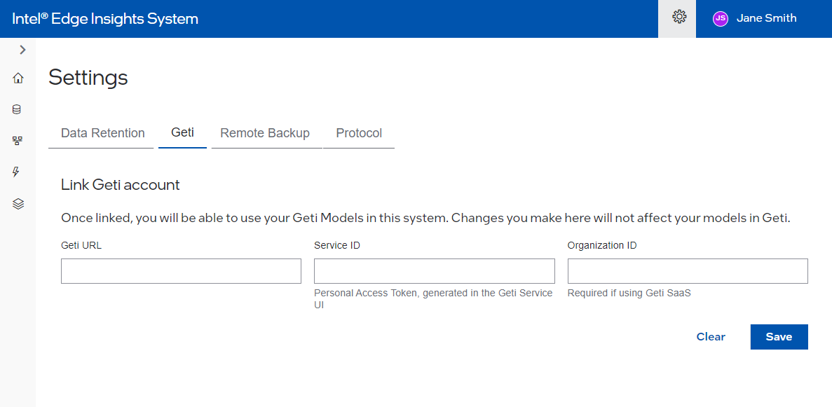
Settings – Geti#
Here user can save Geti URLservice ID and organization ID for Geti and that will be used in select Geti model upload page
Settings – MQTT#
The user can configure the details of the available MQTT broker to allow publishing inference results over the MQTT broker.
The MQTT publishing is disabled by default. The user needs to enable it and provide further details.
Figure 54. Settings – MQTT
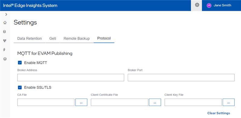
The user can also select “Enable SSL/TLS” if the secured communication is desired. At present, mutual TLS authentication mechanism is supported. Hence, the user is required to provide CA file apart from client certificate and key file.
Click on the “Save Changes” button to save the changes. This action will restart EVAM container in the backend.
Note: The user will not receive any popup for unsaved data on the MQTT page.
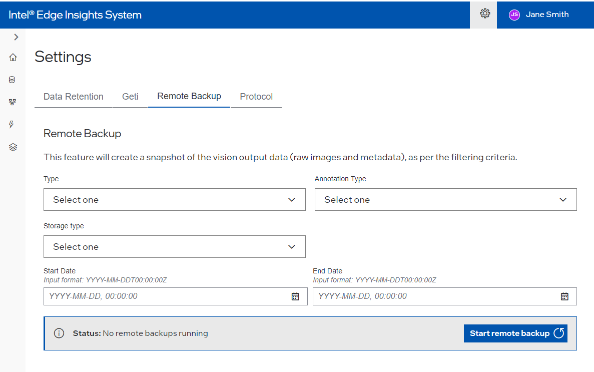
Settings – Remote Backup#
This feature will create a snapshot of the vision output data (raw images and metadata), as per the filtering criteria.
This will take backup of all data for given period and store on selected storage type
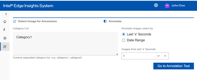
Settings – Data Annotation#
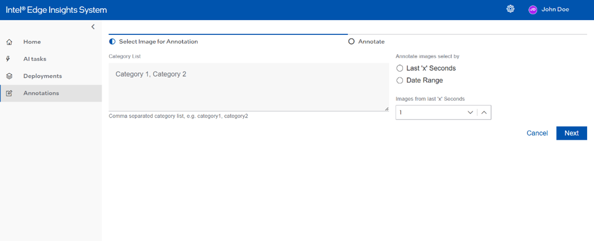
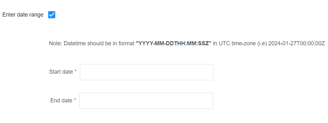
These are the settings related to “Human Annotation” feature of “Data Collection As A Service”. For performing the “Human Annotation”, one is required to identify the images to be used from collected data. For images section, there are 2 options – date range or data from last x seconds. Finally, the CVAT tool is used for performing the annotation. Refer “Intel® Edge Data Collection” for more information on CVAT configurations.
Figure 55. Settings – Data Annotation – Last ‘x’ Seconds
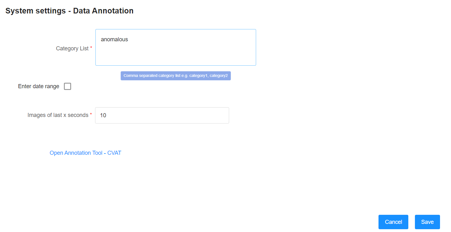
Figure 56. Settings – Data Annotation – ‘Date Range’
Once the configurations are applied, the CVAT tool can be visited using the link available on this configuration page if the Web UI is accessed using system browser from the IPC.
Create a New Model Processing File#
This section will cover how the user can create a new custom model processing file for Intel® Edge Insights System based on the existing model processing file the user created. Users can directly upload the zipped file (e.g. dummy.zip) of the custom model file for testing. Following are the steps to create the custom model zip file. This zip file can be uploaded to Intel® Edge Insights System using ‘add new custom model’ process.
Figure 57. Dummy.zip File Tree
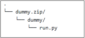
The Model processing file (python) is required to be renamed to ‘run.py’. The path for labels and xml/bin files is decided by Users. The users must ensure the file can be accessed by run.py with a relative path.
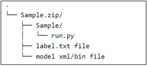
Figure 58. Sample.zip File Tree with the Label and Model Xml/Bin File
Modify the Existing Sample#
This section only mentioned the snippets that must be added or modified within the existing model processing file. The model loading section, pre-processing, and post-processing that the user defines should be maintained.
**
**
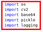
Import
Users can define the library that needs to be used within the file by specifying the library import in this section. Users need to add the highlighted library that Intel® Edge Insights System will utilize to the existing library that has been used.
Figure 59. Import Section Snipped
Initialization Function
This function will initialize the process parameter that needs to be consumed later in processing the model. In the first block, the user needs to change the initialization constructor as shown to reflect the parameter that needs to be obtained from Intel® Edge Insights System.
Figure 60. Initialization Function Section Snipped
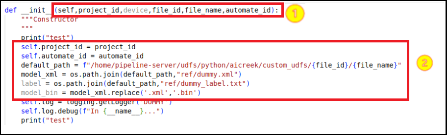
The user needs to add the second block, as shown above, in the existing model processing file and change the model_xml parameter for the .xml model name accordingly to reflect the model that will be used.
default_path parameter is the default file location that is already being defined in the Intel® Edge Insights System. The user does not need to change this parameter else it will cause an error to the application.
Next, the user needs to add the third block in the existing model processing file and change the label parameter accordingly to reflect the label file that will be used.
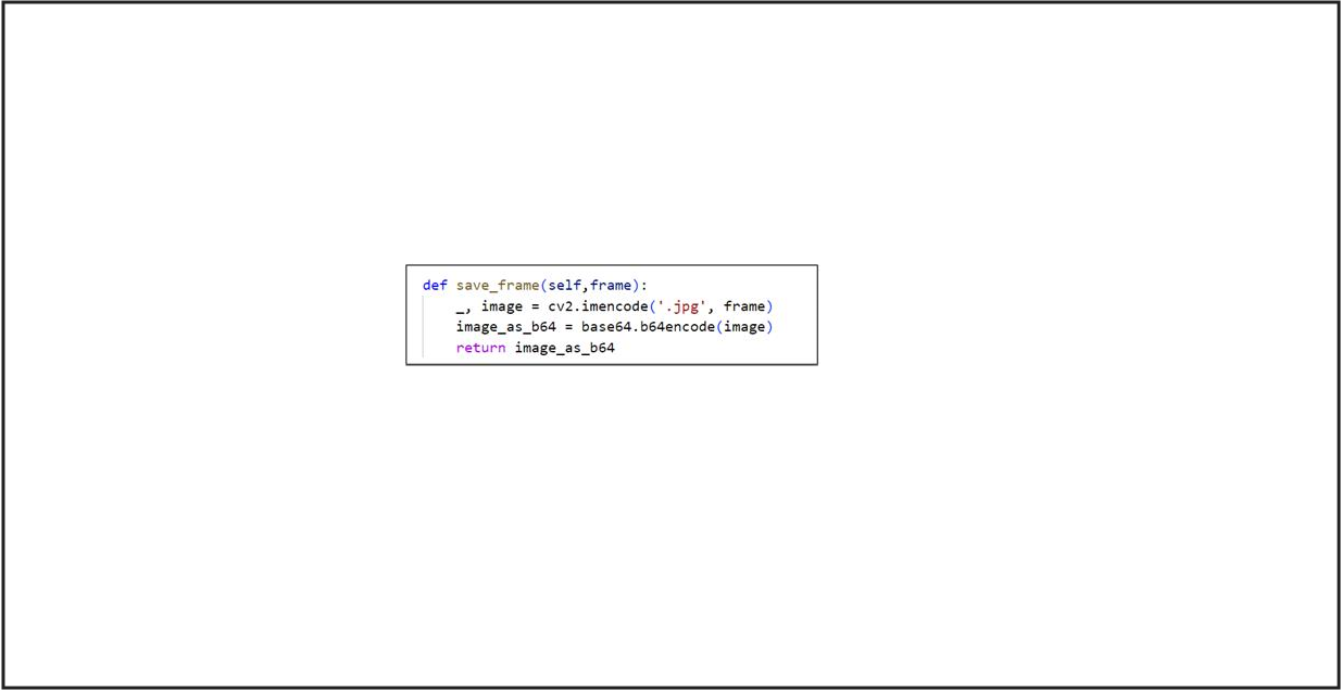
Save Image Function
The user needs to add this function to the existing model processing file. This function will save the inferencing result frame that will be used to visualize the Intel® Edge Insights System output visualization section.
Figure 61. Save Image Function Section Snipped
Process Function
With the existing processing function defined by the model for the specific use case, the user needs to add the below section to make it work with Intel® Edge Insights System.
Figure 62. Process Function Section Snipped
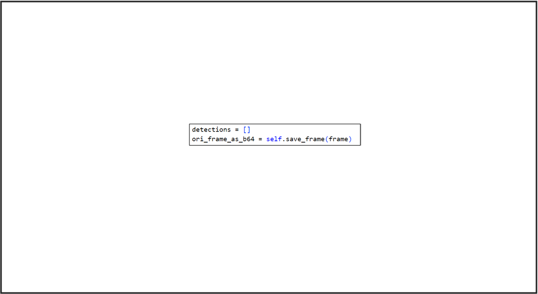
The above section is for saving the inference image as base64 that will be used for the Intel® Edge Insights System visualization.
Figure 63. Saving Metadata and Label Section Snipped
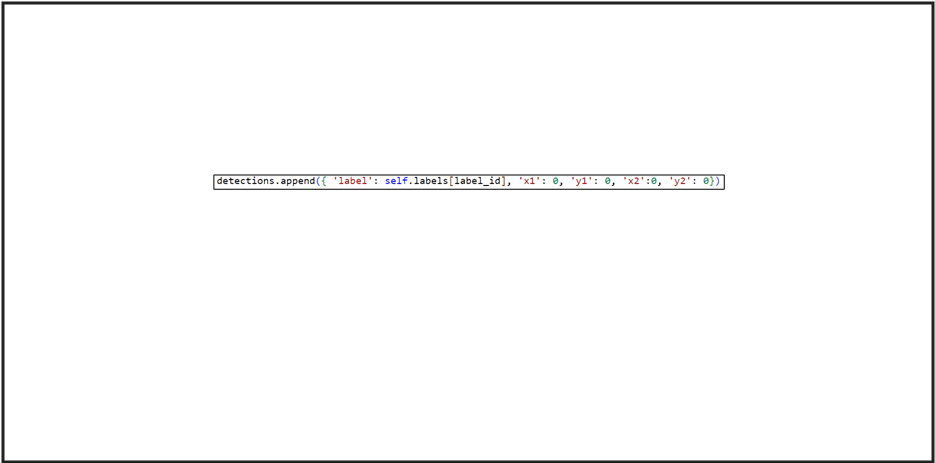
The above section is for saving the metadata and label based on the inferencing result. In the example, the ‘X’ and ‘Y’ coordinates are set to ‘0’ as this model processing file for the classification model. Thus, if the user uses other models that need to draw a bounding box, the coordinate parameter must be changed accordingly.
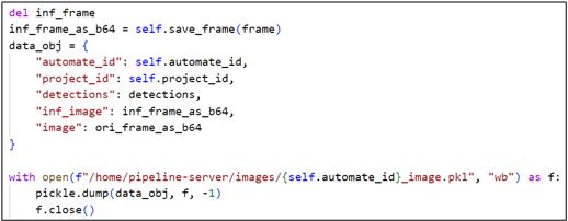
Figure 64. Save the Inference File to Base64 Section Snipped
Model Registry as a Service#
The Intel® Edge Insights System contains “Model Registry as a Service” (MRaaS) microservice. The MRaaS provides REST APIs to manage artifacts, and metadata associated to a registered machine learning (ML) model created using Intel® Geti™.
The documentation of REST APIs of MRaaS can be accessed from the IPC on which Intel® Edge Insights System is installed using https://localhost:5002/docs link.
Intel® Edge Insights System uses MRaaS APIs internally for Intel® Geti™ model related features (e.g. add new Intel® Geti™ model).
Intel® Edge Data Collection#
The Intel® Edge Insights System contains the “Intel® Edge Data Collection” microservice. The service helps in collection and annotation of input video data which can be used for AI model training/fine-tuning and statistical analysis.
The UI in Intel® Edge Insights System allows configuration of “Intel® Edge Data Collection” microservice for “Human Annotation” feature to fetch images and the corresponding annotations for reviewing and updating the annotations using CVAT tool.
CVAT Tool Configuration#
Accessing CVAT from Same System#
Use the following steps to access CVAT tool from the same system where Intel® Edge Insights System is installed:
Identify docker system host IP using following command on terminal:
docker network inspect bridge -f '{{range .IPAM.Config}}{{.Gateway}}{{end}}'
Generally, the IP is found to be 172.17.0.1.
Configure the IP address obtained in step 1 in CVAT_HOST variable. Please refer “Configuring CVAT_HOST variable” for more details.
Accessing CVAT from other Systems in the Network#
Obtain the IP address of the system and configure it in CVAT_HOST variable. Please refer to the “Configuring CVAT_HOST variable” for more details.
Configuring CVAT_HOST Variable#
CVAT_HOST variable is present in IEdgeInsights/build/.env file. The value of this variable can be changed if needed.
Figure 65. CVAT_HOST Variable in IEdgeInsights/build/.env File

If the system is running behind a proxy, then please include the value of CVAT_HOST i.e. IP address used, in no_proxy environment variable in /etc/environment.
Kindly redeploy the project if already running for the configuration change to take effect.
Remote Storage (Optional Settings)#
For remote storage feature, certain environment variables:
DCAAS_STORAGE_DIR, AZURE_STORAGE_CONNECTION_STRING, AZURE_STORAGE_CONTAINER
Need to be set in IEdgeInsights/build/.env. Please refer documentation of “Intel Edge Data Collection” service for more details.
Note: ETCD changes(EIS configuration) get will be reverted to default values when project is deactivated and re-activated.
While using Remote Storage feature of DCaaS, the user needs to provide values of class parameters like anomalous or Person. Please refer DCaaS documentation for more information about these parameters.
These values can be configured in the JSON file so that these can be provided to DCaaS during execution.
To change the values of class parameter, Follow the below steps:
If need to be updated, either for
CLASSIFICATIONorOBJECT_DETECTION, update the corresponding values in gui_config_setting.json file. For example, to updateCLASSIFICATIONchange the value ofFILTER_CLASSIFICATION_THRESHOLD. Limits are in string separated by,and each class are in key-value pair consistingCLASS_NAME:THRESHOLD_LIMIT(i.e) fornon-anomalousvalue should benon-anomalous:0.5, thengui_config_setting.jsonshould be updated as below
{
    "FILTER_CLASSIFICATION_THRESHOLD":"anomalous:0.45,non-anomalous:0.5",
    "FILTER_OBJECT_DETECTION_THRESHOLD":"Person:0.7,Vehicle:0.5"
}
If the values are updated, then we need update the configuration from GUI frontend for DCaaS Remote Storage and click on save.
Troubleshooting#
Please refer Troubleshooting Guide for more details.